
Laser ignition system based diagnostics

a technology of laser ignition system and diagnostics, applied in the field of laser ignition system based diagnostics, can solve the problems of reducing the accuracy of inspection, requiring costly, labor-intensive, time-consuming visual inspection, and adding extensive time and cost to the diagnostics, so as to reduce the need for costly, labor-intensive, and time-consuming inspections. the effect of time and cost reduction

Active Publication Date: 2015-07-16
FORD GLOBAL TECH LLC
View PDF3 Cites 3 Cited by
  • Summary
  • Abstract
  • Description
  • Claims
  • Application Information

AI Technical Summary

Benefits of technology

The patent text describes a method for using a laser ignition system to diagnose engine components and identify potential issues without the need for costly and time-consuming visual inspections. This approach involves initiating cylinder combustion using the laser ignition device, gathering images of the combustion process, and displaying them to an operator for analysis. The operator can then identify degraded components or abnormal combustion characteristics. By making use of existing components and hardware in the engine, this method simplifies the inspection process and reduces costs while maintaining accuracy.

Problems solved by technology

The inventors herein have recognized that the above discussed approaches can add extensive time, cost, and complexity to the diagnostics.
In particular, most of the above approaches require a skilled technician, complex diagnostic tools, specialized laboratory facilities, and time consuming engine teardown.

Method used


Image

  • Laser ignition system based diagnostics
  • Laser ignition system based diagnostics
  • Laser ignition system based diagnostics

Examples


Embodiment Construction

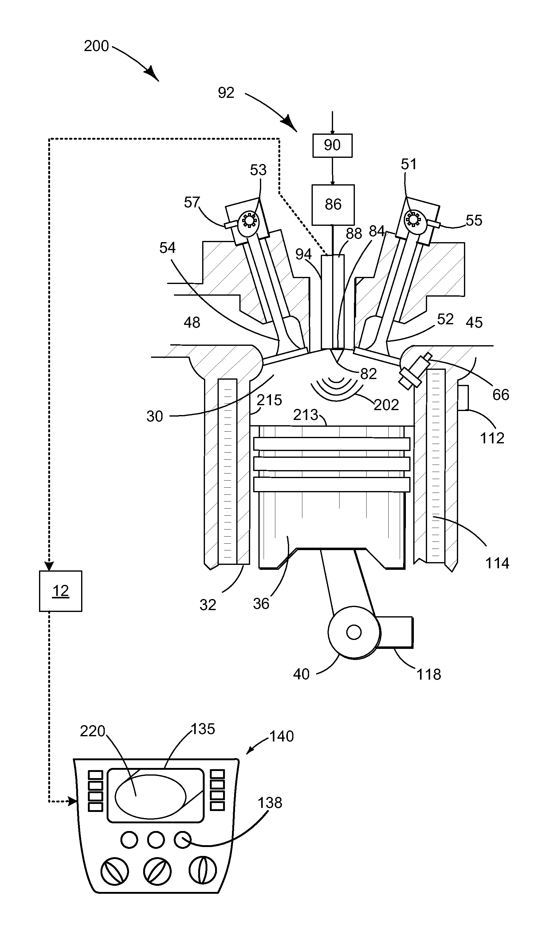
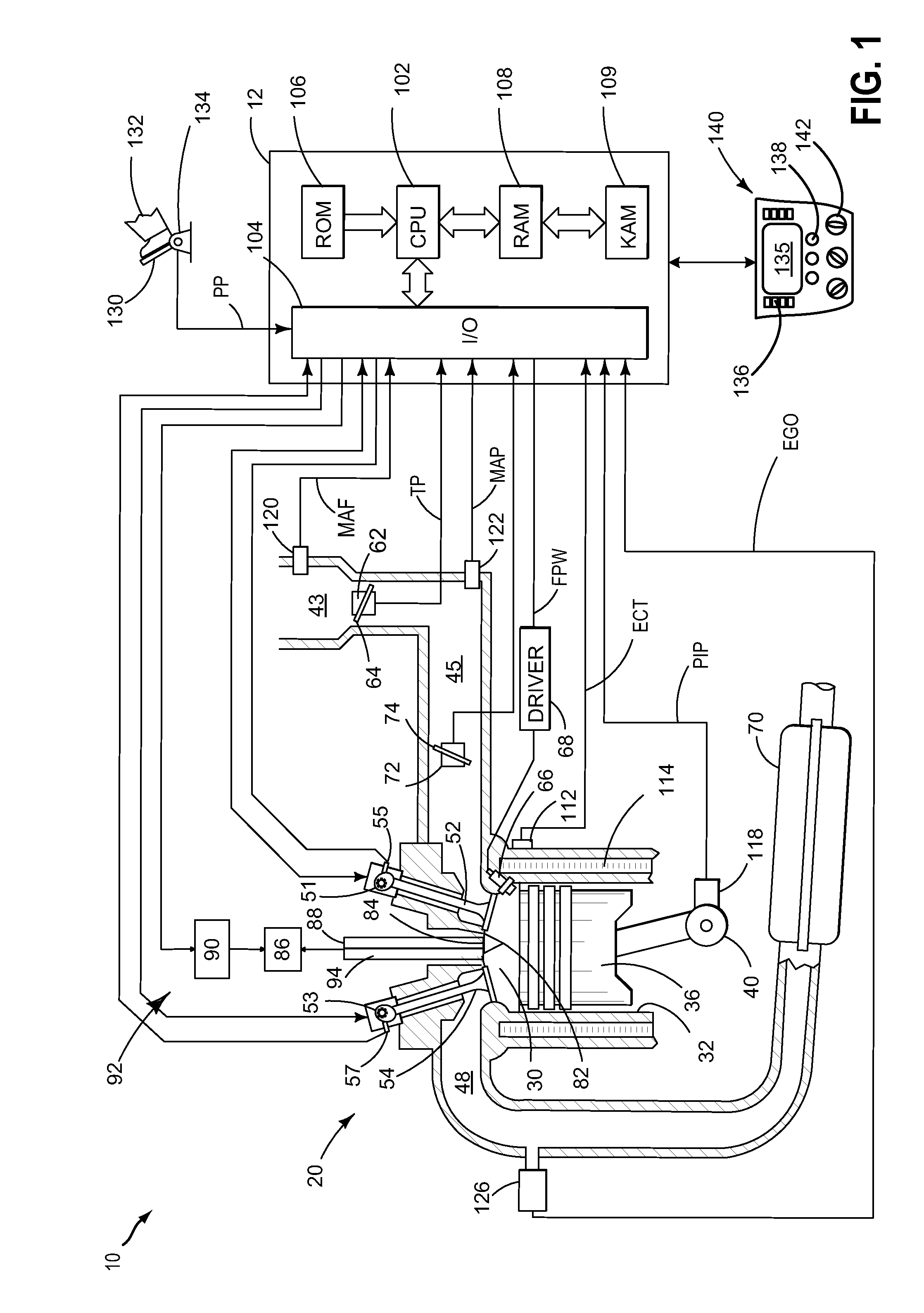
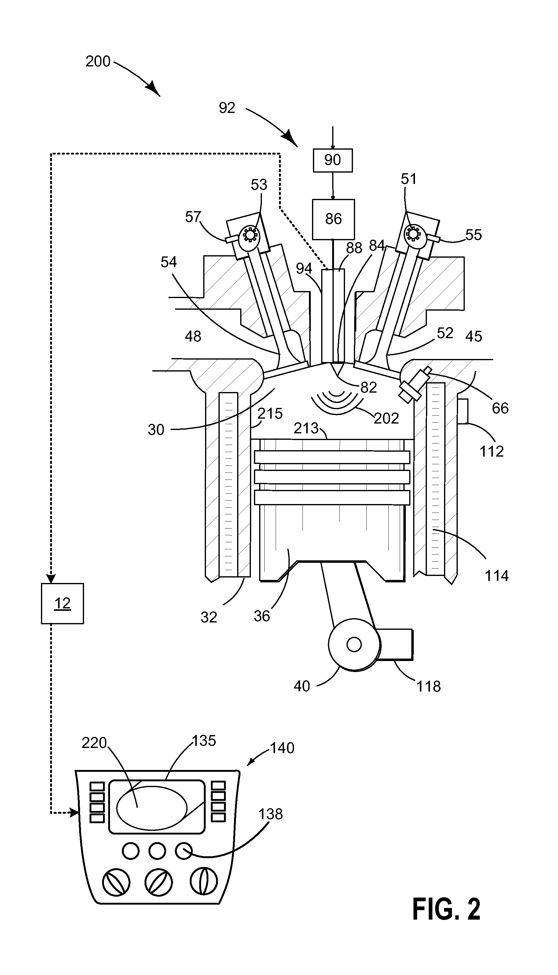
[0019]Methods and systems are provided for diagnosing one or more engine cylinder components using a laser ignition system, such as shown in FIG. 1. As shown at FIGS. 2-3, laser light pulse emission at lower intensities may be used for illuminating the interior of a cylinder while a photodetector captures in-cylinder images. Laser light pulse emission at higher intensities may also be used for initiating combustion while the light generated during combustion is used by the photodetector to capture images of the interior of the cylinder. The generated images may be used to diagnose various in-cylinder components and cylinder combustion parameters. Further still, cam and piston position determination may be accurately performed using the laser light pulse emission, as shown at FIGS. 4-5 allowing for diagnosis of engine camshafts and crankshafts, as discussed at FIG. 8. An engine controller may be configured to perform a control routine, such as the routine of FIG. 6, to diagnose degra...


PUM


Abstract

Methods and systems are provided for using an engine laser ignition system to perform a visual inspection of an engine and diagnose various cylinder components and conditions based on engine positional measurements. Laser pulses may be emitted at a lower power level during an intake and / or exhaust stroke to illuminate a cylinder interior while a photodetector captures images of the cylinder interior. Additionally, laser pulses may be emitted at a higher power level to initiate cylinder combustion while the photodetector captures images of the cylinder interior using the light generated during cylinder combustion.

Description

FIELD[0001]The present application relates to methods and systems for diagnosing an engine using components of a laser ignition system.BACKGROUND AND SUMMARY[0002]Engine system components (such as cylinders, valves, pistons, injectors, etc.) may be intermittently diagnosed for damage incurred during engine operation. The components may also be diagnosed to identify degraded functionality (e.g., incorrect flow, leakage, etc.).[0003]Diagnostics may involve visually inspecting the components for scoring damage, such as by removing a spark plug and obtaining a bore scope to view inside the cylinder. In another approach, described by Yalin et al in US 2006 / 0037572, light from a cylinder spark event and / or combustion flame is used to diagnose for the presence of build-up and contaminants in the cylinder.[0004]The inventors herein have recognized that the above discussed approaches can add extensive time, cost, and complexity to the diagnostics. In particular, most of the above approaches ...

Claims


Application Information

Patent Timeline
IPC IPC(8): F02P23/04B60W20/00G07C5/08G01M15/04
CPCF02P23/04G01M15/042Y10S903/905G07C5/0808B60W20/00G07C5/0825F02P17/00
Inventor MARTIN, DOUGLAS RAYMONDMILLER, KENNETH JAMES
Owner FORD GLOBAL TECH LLC
Learn More