System And Method For Natural Gas Liquefaction

a technology of natural gas liquefaction and system, which is applied in the direction of refrigeration and liquifaction, lighting and heating apparatus, solidification, etc., can solve the problems of limited expansion ratio achieved by a single expander, high refrigerant mass flow rate in these processes, and limited performance of lng process, etc., to achieve the effect of improving refrigeration efficiency

Inactive Publication Date: 2015-07-23
KEPPEL OFFSHORE & MARINE TECH CENT PTE LTD
View PDF7 Cites 19 Cited by
  • Summary
  • Abstract
  • Description
  • Claims
  • Application Information

AI Technical Summary

Benefits of technology

[0007]One objective of this invention is to provide an LNG production system with improved refrigeration efficiency.
[0010]In another embodiment of the LNG production system, the natural gas liquefaction subsystem comprises a gas treatment module for treating the pressurized natural gas so as to make it suitable for being liquefied, a natural gas heat exchange means fluidly / gaseously coupled with the gas treatment module and disposed within the main cryogenic heat exchanger for enabling the passing-through pressurized natural gas to exchange heat with countercurrent refrigerant flows, and a natural gas pressure reduction means fluidly / liquidusly coupled with the natural gas heat exchange means for controlling the reduction of the pressures of the pressurized liquefied natural gas from the natural gas heat exchange means so as to further reduce the temperature of the pressurized liquefied natural gas, yielding LNG and flash gas.

Problems solved by technology

However, the performance of LNG process is limited by several factors, such as the maximum temperature approach limitation of the main cryogenic heat exchanger, and the limited expansion ratio achieved by a single expander.
However, the refrigerant mass flow rate in these processes is high.

Method used


Image

  • System And Method For Natural Gas Liquefaction
  • System And Method For Natural Gas Liquefaction
  • System And Method For Natural Gas Liquefaction

Examples


Embodiment Construction

[0028]The present invention may be understood more readily by reference to the following detailed description of certain embodiments of the invention.

[0029]Throughout this application, where publications are referenced, the disclosures of these publications are hereby incorporated by reference, in their entireties, into this application in order to more fully describe the state of art to which this invention pertains.

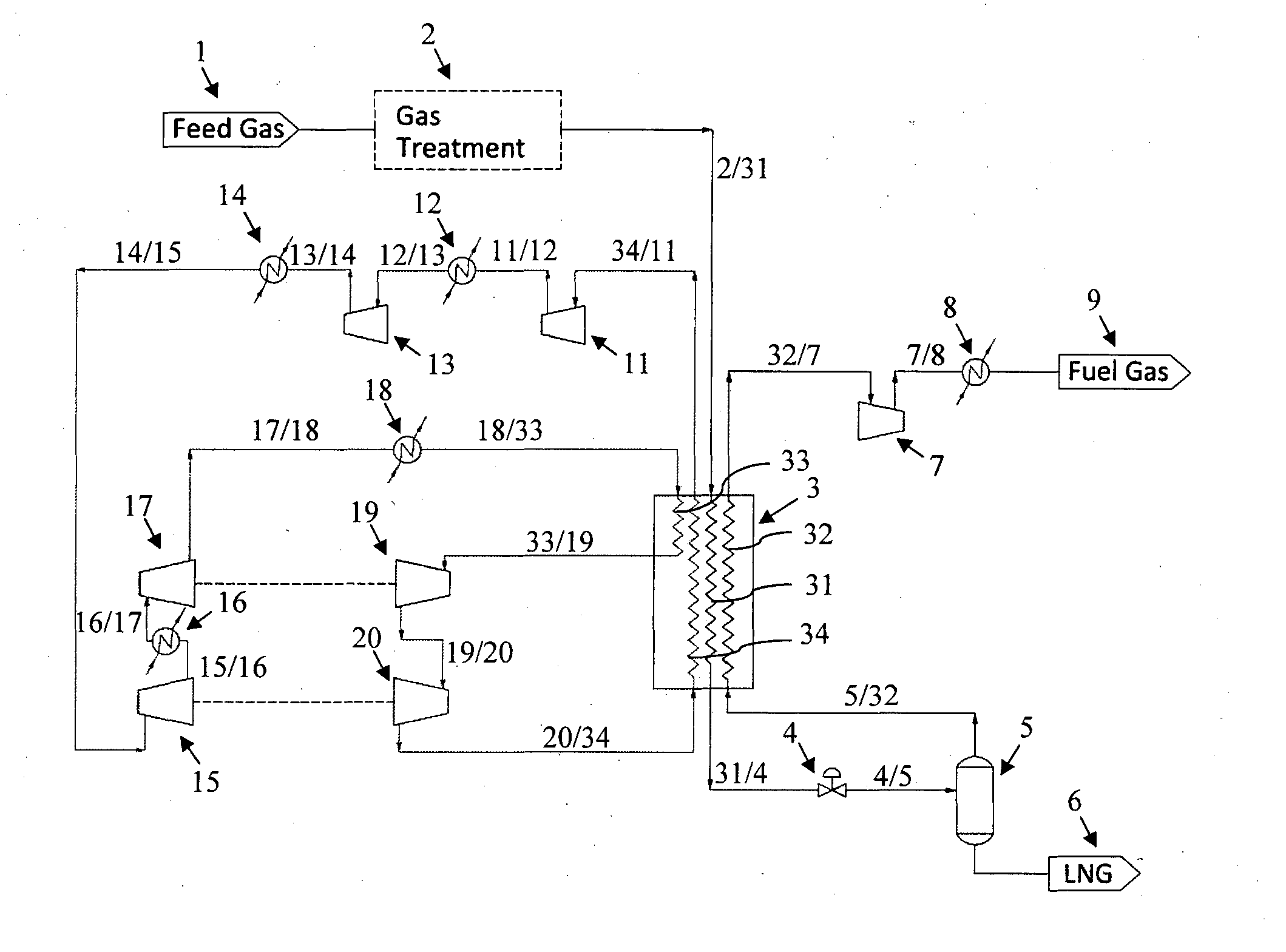
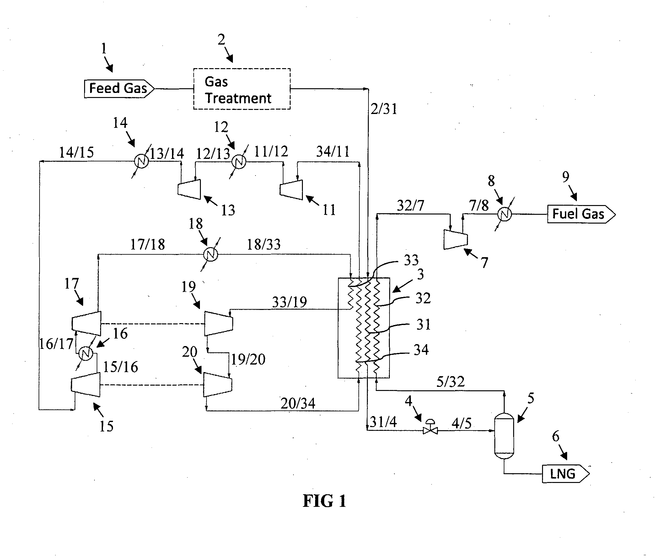
[0030]The present invention provides a system and method to liquefy the natural gas using expander based refrigeration cycle in a simple and efficient way. The system and method uses turboexpanders in series arrangement, resulting in the advantages of simplicity and flexibility, low refrigerant flow rate requirement, low expansion ratio requirement for each expander, and competitive efficiency and power consumption, when compared with the existing prior art processes.

[0031]Referring now to FIG. 1, there is provided an LNG production system in accordance with one embodim...


PUM


Abstract

The present invention provides an LNG production system and method with improved refrigeration. The refrigeration is achieved by a refrigeration device comprising a plurality of refrigerant compressors (11, 13, 15, 17) configured into a series arrangement to perform multi-stage compressions of a refrigerant, a plurality of aftercoolers (12, 14, 16, 18) each of which being coupled to each of the plurality of refrigerant compressors to cool the compressed refrigerant, a plurality of turboexpanders (19, 20) coupled to the last aftercooler (18) and configured into a series configuration to perform multi-stage expansions of the compressed refrigerant, and a plurality of refrigerant heat exchange means (33, 34) coupled to both the first (11) of the plurality of refrigerant compressors and the last (20) of the plurality of turboexpanders, so that all components form a close refrigeration cycle.

Description

FIELD OF THE INVENTION[0001]The present invention relates generally to the technology of natural gas liquefaction, and more particularly to a system and method for natural gas liquefaction employing a plurality of turboexpanders configured into a series arrangement.BACKGROUND OF THE INVENTION[0002]To transport the natural gas in a more efficient way, it is important to liquefy it into liquefied natural gas (LNG) for transportation, which enables to shrink the volume of the natural gas by 600 times so it can be shipped to customers in other parts of the world. Many LNG liquefaction plants utilize a refrigeration cycle with mixed refrigerants where cooling is generally achieved by heat exchange using refrigerant with one or more compositions including propane, propylene, ethane, ethylene, methane and nitrogen or mixtures thereof, in a closed loop or open loop configuration. Mixed refrigerant cycles are efficient as they can closely approach the cooling curve of the natural gas and mul...

Claims


Application Information

Patent Timeline
Patent Type & Authority Applications(United States)
IPC IPC(8): F25J1/00F25J1/02
CPCF25J1/0203F25J1/0022F25J1/004F25J1/005F25J1/0072F25J1/0204F25J1/0288F25J2270/16F25J1/0052
Inventor SHENG, XIAOXIACHONG, WEN SINFOO, KOK SENG
Owner KEPPEL OFFSHORE & MARINE TECH CENT PTE LTD
Why Eureka
Try Eureka