Apparatus for detecting temperature of semiconductor elements for power conversion

a technology of power conversion and apparatus, which is applied in the direction of dc-ac conversion without reversal, heat measurement, instruments, etc., can solve the problems of enlargement of the temperature range of the restricted use of the switching element, inability to reliably protect the switching element from overheating, and inability to perform overheat protection processes. , to achieve the effect of preventing the semiconductor element from overheating, preventing enlargement of the temperature range, and restricting

Active Publication Date: 2015-07-23
DENSO CORP
View PDF10 Cites 24 Cited by
  • Summary
  • Abstract
  • Description
  • Claims
  • Application Information

AI Technical Summary

Benefits of technology

[0012]In the above embodiment, the temperature signal outputs are provided for the respective power-conversion semiconductor elements. This allows the microcomputer to detect the temperature of each of the plurality of power-conversion semiconductor elements. Hence, even though a prespecified one of the switching elements is initially assumed to be hottest during use of the system, another switching element may actually be hottest among the switching elements during use due to aging or the like of the system. Even in such a case, the microcomputer is able to determine which semiconductor element is hottest among the plurality of switching elements. It is thus possible to prevent the semiconductor elements from overheating and prevent enlargement of a temperature range where use of the system is restricted.
[0013]In addition, in the above embodiment, the temperature signal outputted from at least one of the plurality of temperature signal outputs is input directly to the microcomputer without passing through the at least one input-output interface. Therefore, even if the at least one input-output interface fails, paths can be ensured between the microcomputer and the temperature signal outputs other than the at least one of the temperature signal outputs that is not connected to the at least one input-output interface. Even if the at least one input-output interface fails, this can achieve fail-safe, such as power saving, and can thus prevent substantial degradation of the reliability of the system.
[0014]In addition, in the above embodiment, signal transferring paths between the microcomputer and the other two or more temperature signal outputs can be established by using the input-output interface. The input-output interface is configured such that the number of output ports is less than the number of input ports. Therefore, the number of input ports of the microcomputer required to detect the temperatures of the respective power-conversion semiconductor elements can be reduced less than the total number of power-conversion semiconductor elements. This allows the apparatus to be downsized and costs of the apparatus to be reduced.
[0016]In the above other embodiment, the temperature signal outputs are provided for the plurality of power-conversion semiconductor elements, one for each power-conversion semiconductor element. The microcomputer has the plurality of input ports for respectively receiving the temperature signals from the respective temperature signal outputs. That is, in the microcomputer is configured such that the number of the temperature signal outputs is equal to the number of the input ports. Thus, the microcomputer is able to detect the temperatures of the respective whole power-conversion semiconductor elements. Even though a prespecified one of the switching elements is initially assumed to be hottest during use of the system, another switching element may actually be hottest among the switching elements during use due to aging or the like of the system. Even in such a case, the microcomputer is able to determine which semiconductor element is hottest among the plurality of switching elements. It is thus possible to prevent the semiconductor elements from overheating and prevent enlargement of a temperature range where use of the system is restricted.

Problems solved by technology

There is a disadvantage that, if the power converter is not configured to detect a temperature of such another switching element, all the switching elements couldn't be reliably protected from overheating based on the detected temperature of the prespecified one of the switching elements assumed at the time of designing to be hottest during use.
However, in such a configuration, there is a disadvantage that the overheat protecting process may be performed even though the actual temperatures of the switching elements have not yet reached the upper-limit temperature, and a temperature range where use of the switching elements is restricted may enlarge.
Power-conversion semiconductor elements, whether switching elements or not, may suffer from such disadvantages.

Method used


Image

  • Apparatus for detecting temperature of semiconductor elements for power conversion
  • Apparatus for detecting temperature of semiconductor elements for power conversion
  • Apparatus for detecting temperature of semiconductor elements for power conversion

Examples


first embodiment

[0032]There will now be explained a temperature detection apparatus applied to a vehicle-mounted power converter (a three-phase inverter) in accordance with a first embodiment of the present invention with reference to the accompanying drawings.

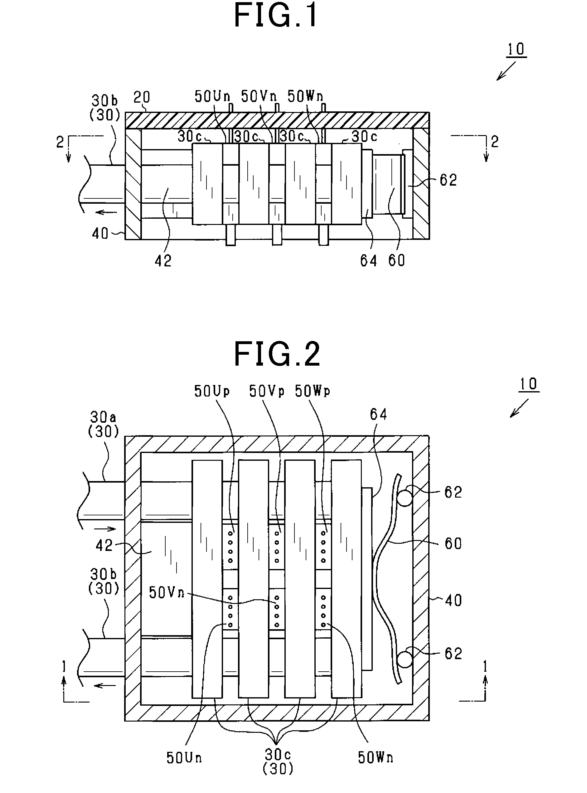
[0033]The three-phase inverter of the first embodiment will be explained with reference to FIGS. 1 and 2.

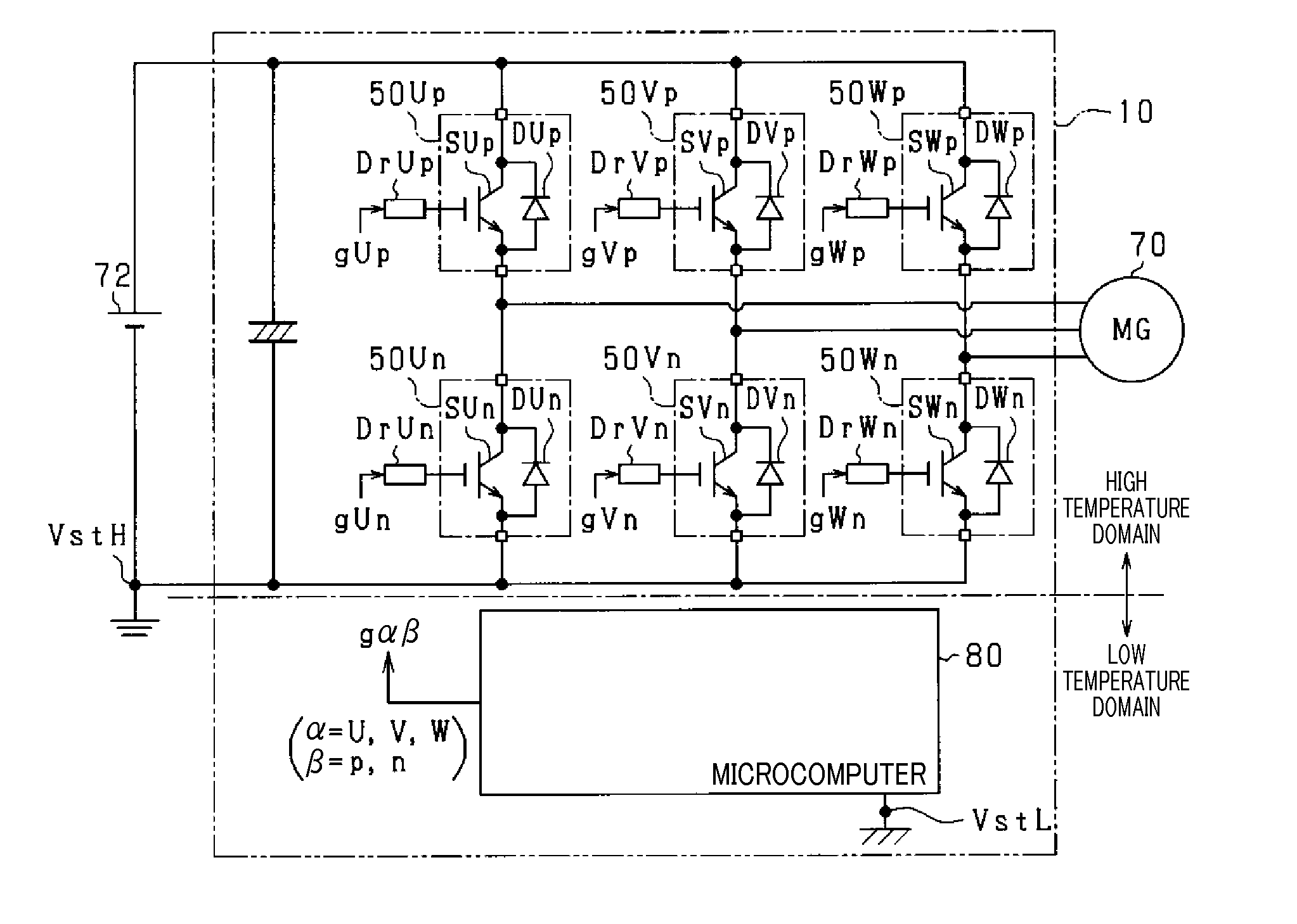
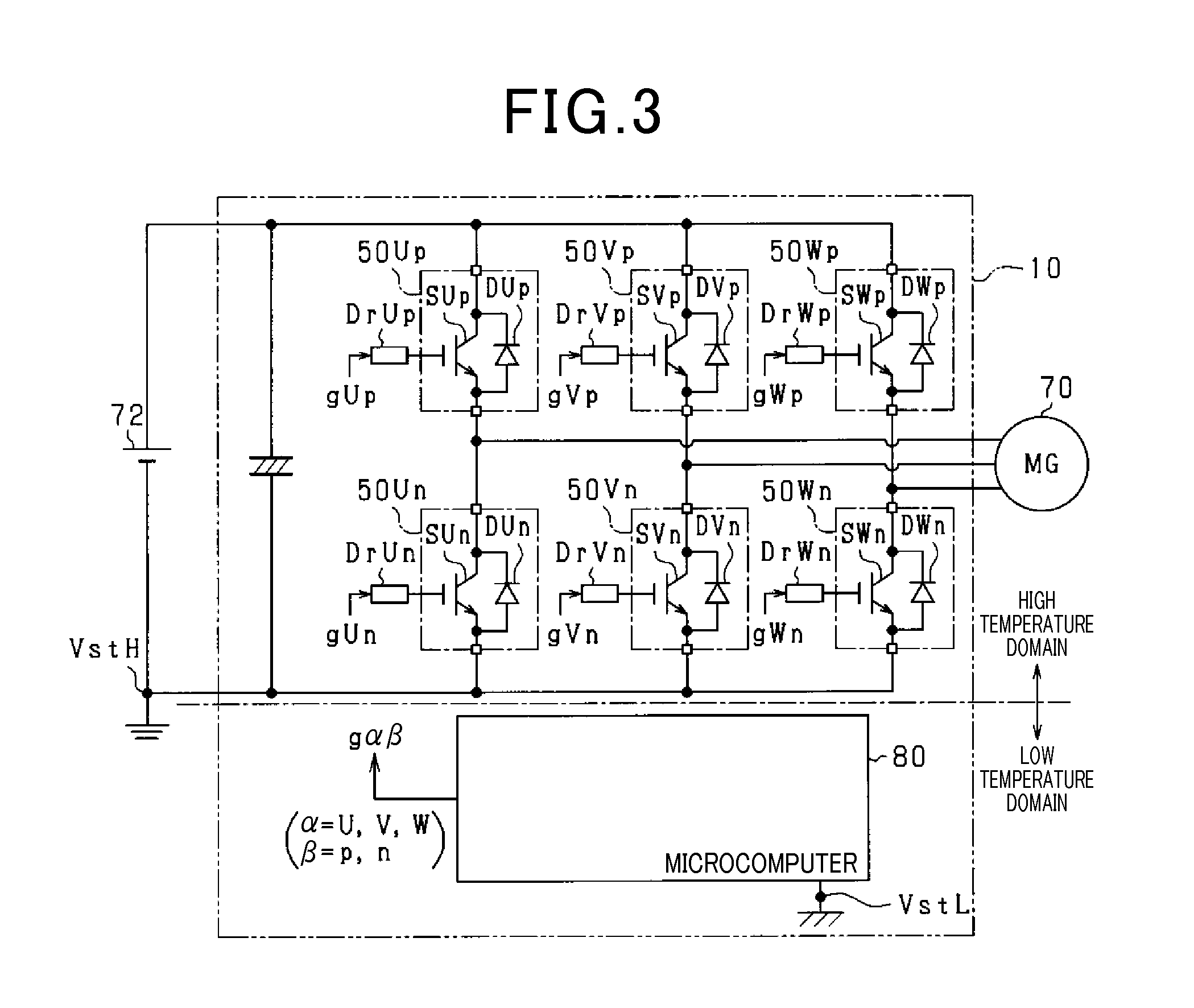
[0034]As shown in FIGS. 1 and 2, the three-phase inverter 10 includes a circuit board 20, a cooler 30, a frame 40, U-, V-, W-phase upper-arm semiconductor modules 50Up, 50Vp, 50Wp, and U-, V-, W-phase lower-arm semiconductor modules 50Un, 50Vn, 50Wn.

[0035]Each semiconductor module 50αβ (α=U, V, W: β=p, n) is a member, into which a switching element, a freewheel diode electrically connected in anti-parallel with the switching element, and a temperature-sensitive diode for detecting a temperature of the switching element are modularized. In the present embodiment, an insulated gate bipolar transistors (IGBT) is used as the switching element....

second embodiment

[0078]There will now be explained a second embodiment of the present invention. Only differences of the second embodiment from the first embodiment will be explained with reference to the accompanying drawings.

[0079]As shown in FIG. 6, the microcomputer 80 of the present embodiment includes first to sixth input ports t1-t6. The first to third input ports T1, T2, T3 are electrically connected directly to outputs of the U-, V-, W-phase upper-arm photocouplers CUp, CVp, CWp via U-, V-, W-phase upper-arm electrical paths LUp, LVp, LWp. Fourth to sixth input ports T4, T5, T6 of the microcomputer 80 are electrically connected directly to outputs of the U-, V-, W-phase lower-arm photocouplers CUn, CVn, CWn via U-, V-, W-phase lower-arm electrical paths LUn, LVn, LWn. In the present embodiment, the α-phase upper- and lower-arm electrical paths Lαp, Lαn (α=U, V, W) may use the wiring pattern of the circuit board 20.

[0080]The present embodiment described above can also prevent each of the six...

third embodiment

[0081]There will now be explained a third embodiment of the present invention. Only differences of the third embodiment from the first embodiment will be explained with reference to the accompanying drawings. In the present embodiment, a two-motor control system including two motor generators (rotating electric machines) is used as a control system. More specifically, as shown in FIG. 7, the control system includes an buck-boost converter 90, a first inverter 100, a first motor generator 101, a second inverter 102, a second motor generator 103, and a microcomputer 80. Each of the motor generators 101, 103 may be a permanent magnet synchronous electrical motor. Elements having similar functions as in the first embodiment (see FIG. 1) are assigned the same numbers.

[0082]The buck-boost converter 90 includes an input capacitor 91, a reactor 92, voltage-transformation switching elements SCpa, SCpb, SCna, SCnb, freewheel diodes DCpa, DCpb, DCna, DCnb electrically connected in anti-paralle...


PUM

PropertyMeasurementUnit
threshold temperature Tγaaaaaaaaaa

Abstract

An apparatus for detecting temperatures of power-conversion semiconductor elements, which is applicable to a system including a plurality of power-conversion semiconductor elements and a plurality of temperature signal outputs for outputting temperature signals correlated to temperatures of the respective semiconductor elements. In the apparatus, the temperature signal outputted from at least one of the temperature signal outputs is input directly to a microcomputer without passing through at least one input-output interface. The temperature signals outputted from the other two or more temperature signal outputs are input to a plurality of input ports of the at least one input-output interface sequentially connected to an output of the interface. The microcomputer detects the temperatures of the respective semiconductor elements based on the temperature signals received from the output port of the at least one input-output interface and the temperature signal received directly from the at least one of the temperature signal outputs.

Description

CROSS-REFERENCE TO RELATED APPLICATION[0001]This application is based on and claims the benefit of priority from earlier Japanese Patent Applications No. 2013-255769 field Dec. 11, 2013 and No. 2014-220603 filed Oct. 29, 2014, the descriptions of which are incorporated herein by reference.BACKGROUND[0002]1. Technical Field[0003]The present invention relates to an apparatus for detecting temperatures of semiconductor elements for power conversion.[0004]2. Related Art[0005]Conventionally, a known power converter, as disclosed in Japanese Patent Application Laid-Open Publication No. 2008-206345, includes a plurality of switching elements, such as insulated gate bipolar transistors (IGBTs), is configured such that temperatures of some of the plurality of switching elements can be detected by temperature sensing elements. More specifically, in such a power converter, a prespecified one of the switching elements is assumed to be hottest among the switching elements during use. In such a p...

Claims


Application Information

Patent Timeline
Patent Type & Authority Applications(United States)
IPC IPC(8): G01K7/01G01K13/00H02P27/06
CPCG01K7/01G01K13/00H02P27/06G01K1/026G01K2205/00H02M1/32H02M7/48H02P29/68F02N2011/0888H02M1/327
Inventor DAITOKU, OSAMUFUJITA, HIROSHI
Owner DENSO CORP
Why Eureka
Try Eureka