
Photosensitive Resin Composition

a technology of resin composition and photosensitive resin, which is applied in the direction of photosensitive materials, photomechanical equipment, instruments, etc., can solve the problems of reducing the energy conversion ratio of mercury lamps, contributing to image degradation, and affecting the use of ultraviolet mercury lamps as radiation sources, etc., and achieve good exposure latitude

Active Publication Date: 2015-07-23
MACDERMID PRINTING SOLUTIONS
View PDF2 Cites 1 Cited by
  • Summary
  • Abstract
  • Description
  • Claims
  • Application Information

AI Technical Summary

Benefits of technology

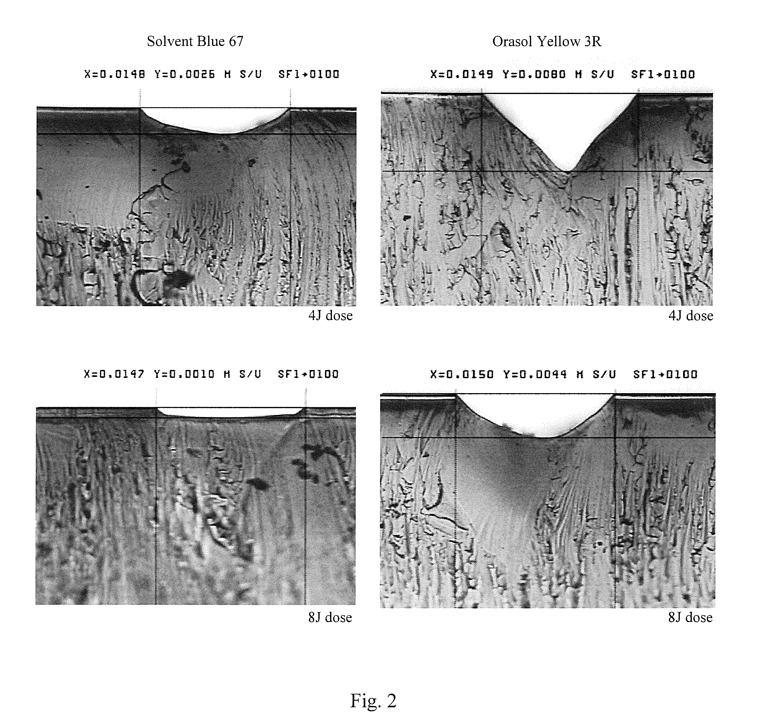
The present invention provides a photocurable composition that has good exposure latitude, meaning it can be exposed to actinic radiation without being negatively affected. Additionally, it can be exposed to LED source at a chosen wavelength while still having good exposure latitude. The composition also produces fine highlight dots without filling plate reverses. The presence of a dye that matches the wavelength of the exposing light results in a relief image with improved exposure latitude.

Problems solved by technology

Doing the back exposure first may result in damaging the black mask during the plate handling, thus contributing to image degradation.
However, the use of ultraviolet mercury lamps as a radiation source suffers from several disadvantages including environmental concerns from mercury and the generation of ozone as a by-product.
Further, mercury lamps typically have lower energy conversion ratio, require warm-up time, generate heat during operation, and consume a large amount of energy when compared with LEDs.
In addition, mercury lamps are characterized by a broad spectral output, in addition to the UV radiation, much of which is not useful for curing and can damage substrates and presents hazards to personnel.
However, the downside is that as exposure times are increased to hold finer dots, reverses often start to close up.

Method used


Image

  • Photosensitive Resin Composition
  • Photosensitive Resin Composition

Examples


Embodiment Construction

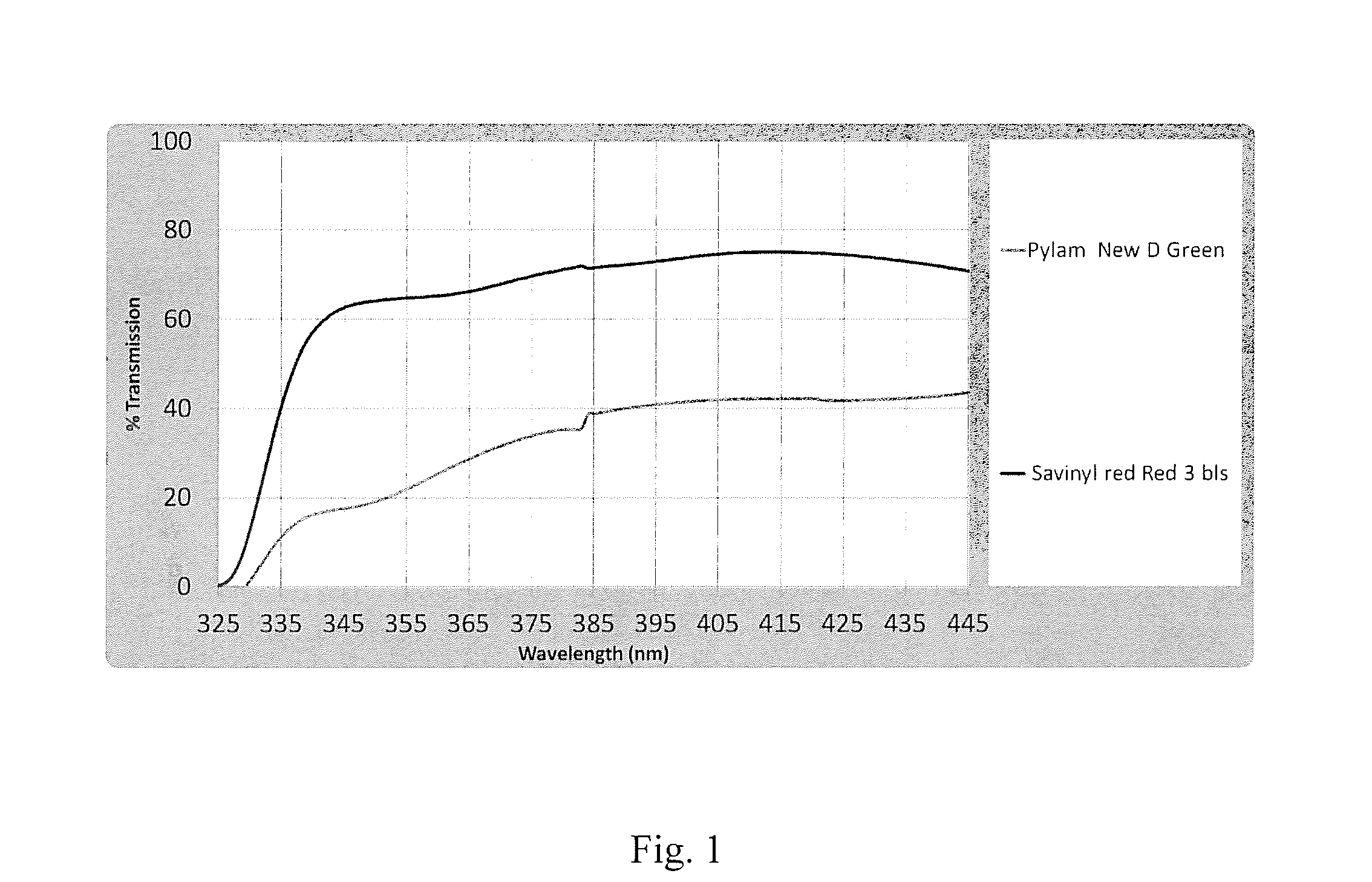
[0042]The present invention relates generally to a method of making a photosensitive relief image printing element from a photosensitive printing blank, wherein the photosensitive printing blank comprises a support, at least one photocurable layer upon the support, wherein the at least one photocurable layer is capable of being selectively crosslinked and cured upon exposure to actinic radiation at a desired wavelength region and wherein the at least one photocurable layer comprises (a) at least one elastomeric binder, (b) at least one ethylenically unsaturated monomer, (c) a photoinitiator having a favorable absorption profile in the desired wavelength region used for exposing the at least one photocurable layer to actinic radiation, and (d) a dye, wherein the dye exhibits a suitable percent transmission as measured with a UV spectrophotometer at the desired wavelength region used for exposing the at least one photocurable layer to actinic radiation, and optionally an infrared abla...


PUM

PropertyMeasurementUnit
concentrationaaaaaaaaaa
transmittanceaaaaaaaaaa
wavelengthaaaaaaaaaa

Abstract

A photosensitive printing blank having is described. The photosensitive printing blank comprises at least one photocurable layer that is capable of being selectively crosslinked and cured upon exposure to actinic radiation at a desired wavelength region comprising (a) at least one elastomeric binder, (b) at least one ethylenically unsaturated monomer, (c) a photoinitiator having a favorable absorption profile in the desired wavelength region used for exposing the at least one photocurable layer to actinic radiation, and (d) a dye, wherein the dye exhibits a suitable percent transmission as measured with a UV spectrophotometer at the desired wavelength region used for exposing the at least one photocurable layer to actinic radiation, and optionally an infrared ablatable layer disposed on the at least one photocurable layer. A method of making a relief image printing element from the photosensitive printing blank is also described.

Description

FIELD OF THE INVENTION[0001]The present invention relates generally to a method of making a flexographic printing element having improved exposure latitude.BACKGROUND OF THE INVENTION[0002]Flexography is a method of printing that is commonly used for high-volume runs. Flexography is employed for printing on a variety of substrates such as paper, paperboard stock, corrugated board, films, foils and laminates. Newspapers and grocery bags are prominent examples. Coarse surfaces and stretch films can be economically printed only by means of flexography.[0003]Flexographic printing plates are relief plates with image elements raised above open areas. Generally, the plate is somewhat soft, and flexible enough to wrap around a printing cylinder, and durable enough to print over a million copies. Such plates offer a number of advantages to the printer, based chiefly on their durability and the ease with which they can be made. A typical flexographic printing plate as delivered by its manufac...

Claims


Application Information

Patent Timeline
Patent Type & Authority Applications(United States)
IPC IPC(8): G03F7/004G03F7/038G03F7/20
CPCG03F7/0045G03F7/20G03F7/038G03F7/029G03F7/031G03F7/202G03F7/027
Inventor BALDWIN, KYLE P.BARBOZA, MIGUEL A.O'BRATE, KERRYSANCHEZ, ROGELIO
Owner MACDERMID PRINTING SOLUTIONS
Learn More