Power station arrangement with high-temperature storage unit

a technology of storage unit and power station, which is applied in the direction of steam use, machine/engine, energy input, etc., can solve the problems of ohmic power loss, increased heat demand, and cooling during charging, so as to achieve energetically efficient utilization of thermal energy, improve efficiency, and cover heat demand

Inactive Publication Date: 2015-07-23
SIEMENS AG
View PDF6 Cites 19 Cited by
  • Summary
  • Abstract
  • Description
  • Claims
  • Application Information

AI Technical Summary

Benefits of technology

[0020]According to the invention, the extraction of waste heat, that is to say thermal energy of the energy generating unit which is not used for a power generation process, for example, therefore enables the high-temperature storage unit to be supplied with heat via the piping system. A supply of the high-temperature storage unit for example via electrically operated heating elements is therefore no longer necessary, or no longer exclusively necessary, but the heat supply can be achieved by means of a direct extraction of heat energy from the energy generating unit. By the extraction of waste heat from the energy generating unit the overall efficiency of the power station arrangement can be advantageously improved.
[0022]According to the invention, it is furthermore provided that the piping system includes a first heat exchanger which is designed for utilizing a steam flow supplied by the energy generating unit and tapped from a steam pipe for the transfer of heat to an air flow, which air flow is fed via the piping system to the high-temperature storage unit. The steam flow according to the embodiment in this case serves especially for energy generation or energy utilization in a steam process. Consequently, the thermal energy provided by the energy generating unit primarily serves for steam preparation, wherein only some of this steam energy is provided for supplying the high-temperature storage unit with heat. This ensures an energetically efficient utilization of the thermal energy.
[0023]According to the invention, the heat demand of the high-temperature storage unit during the charging process, but also during a stationary operation, can be covered by thermal energy of the energy generating unit. According to the invention, the heat demand can generally be covered during a normal operation. A normal operation of the high-temperature storage unit in this case comprises all operating modes which may be necessary for the use of a high-temperature storage unit. Especially to be counted among these are: starting operation, load operation during a charging process or a discharging process, partial load operation during a charging process or a discharging process, stationary operation, heat retention operation, etc. In addition to the already mentioned efficiency improvement during operation of the power station arrangement, at the same time self-discharging losses of the high-temperature storage unit, which would result on account of fluctuations of the operating temperature, can therefore also be reduced. Moreover, the high-temperature storage unit is sometimes ready for operation more quickly as a result of the heat supply according to the invention and therefore increases the flexibility of the power generation of the power station arrangement.
[0027]Since, moreover, air constitutes a gas mixture which is easy to manage and is inexpensive, an advantageous heat supply of the metal storage unit is possible according to the embodiment.
[0035]The heat flux discharging from the high-temperature storage unit is consequently directed again a cyclic circuit to a place upstream with regard to the high-temperature storage unit in order to thermally condition there the air flow which is fed to the high-temperature storage unit. A heat loss from the high-temperature storage unit can therefore be reduced, especially during an exothermic discharging process of the high-temperature storage unit.
[0039]According to another embodiment of the invention, it is provided that the piping system comprises an inlet point arranged on the upstream side with regard to the high-temperature storage unit, which is designed for feeding back an air flow discharged from the high-temperature storage unit into the piping system in order to mix this with the air flow which is fed to the high-temperature storage unit. The air discharging from the high-temperature storage unit and having thermal energy is consequently fed back to an inlet point of the piping system which is arranged on the upstream side with regard to the high-temperature storage unit. As a result of the mixing process between new air, i.e. air not yet fed to the high-temperature storage unit, and used air, i.e. air already fed to the high-temperature storage unit, an especially efficient transfer of heat is carried out. This reduces the thermal loss capacity of the high-temperature storage unit significantly.

Problems solved by technology

Since the charging process in the case of such storage units procedes endothermically, moreover, cooling takes place during the charging which can only be reduced or prevented by sufficient heat being fed to the storage unit.
In contrast to this, high-temperature storage units, however, during the discharging process release thermal energy which is generated during exothermic discharging processes and consequently has to be dissipated.
As a consequence of increasing this charging current density, the ohmic power loss also increases during the charging process, which can in turn be partially made available to the storage unit as waste heat output.
A disadvantage to the previously described method for heat supply of a high-temperature storage unit is on the one hand that the provision of the thermal output can be achieved only by expenditure of additional energy and therefore by incurring additional costs.
A heat supply by means of suitable heating elements integrated into the storage unit especially necessitates a high constructional cost.
A disadvantage of these solutions known from the prior art, however, is that the thermal energy which is fed to the high-temperature battery or to the solid oxide fuel cell sometimes does not allow sufficiently advantageous energetic utilization of the primary heat source.
When supplying a high-temperature storage unit by means of an increased waste heat output in the case of increased charging current density, however, a chemical or even physical degradation of the storage unit is sometimes to be feared.

Method used


Image

  • Power station arrangement with high-temperature storage unit
  • Power station arrangement with high-temperature storage unit
  • Power station arrangement with high-temperature storage unit

Examples


Embodiment Construction

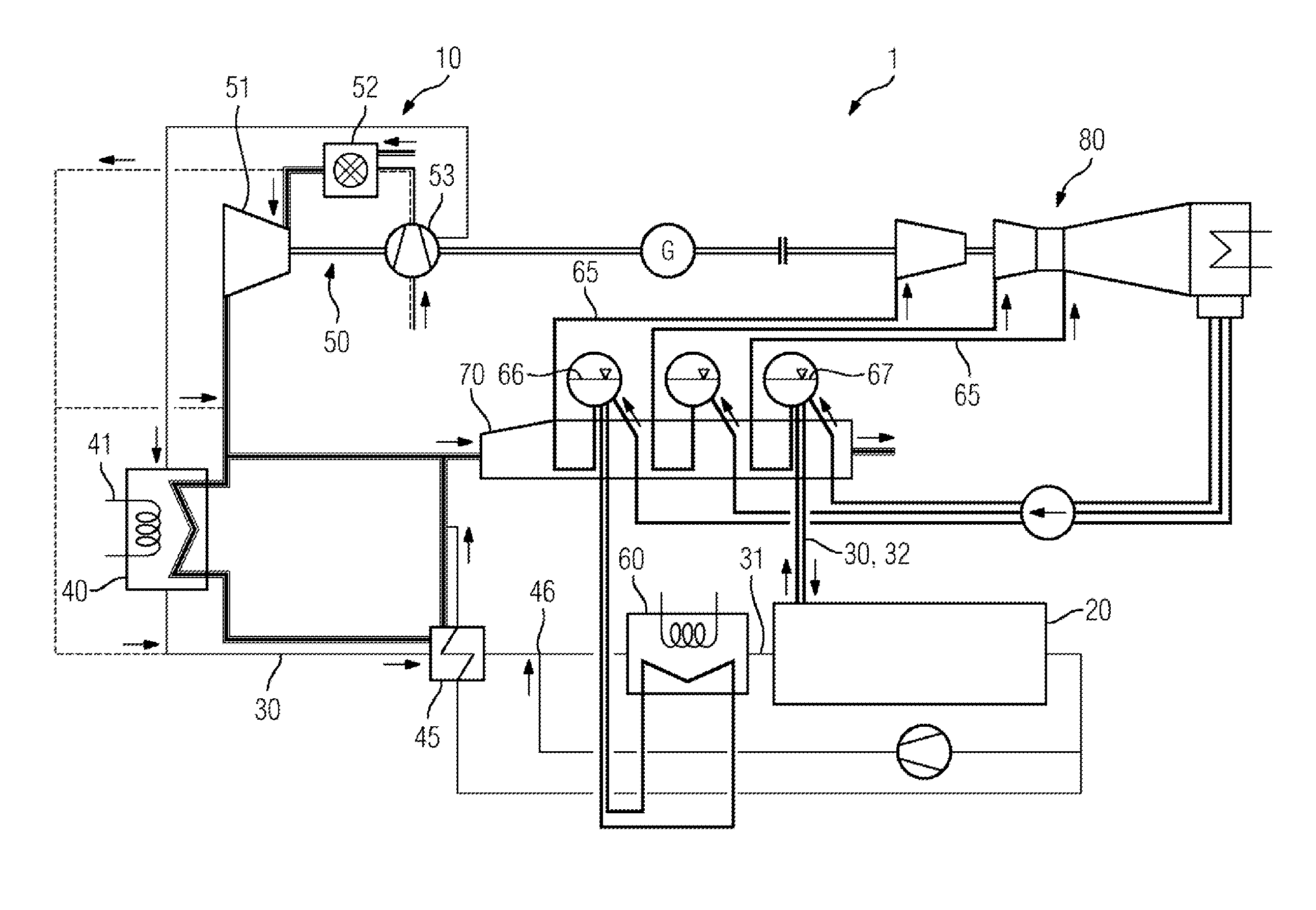
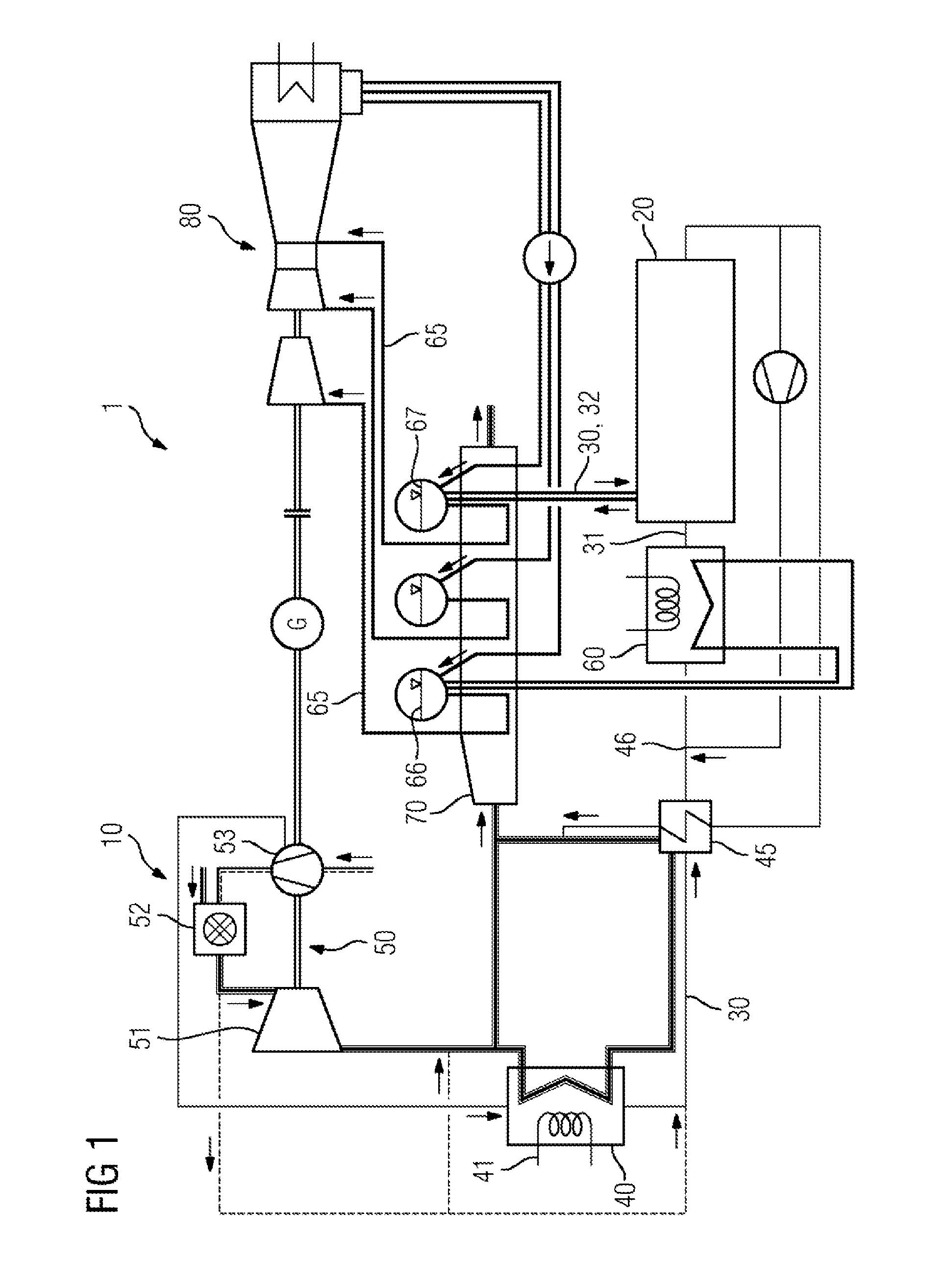
[0052]FIG. 1 shows a schematic view of a first embodiment of the power station arrangement 1 according to the invention. In this case, a gas turbine 50 is incorporated as an energy generating unit 10 and has an expansion stage 51, a combustion chamber 52 connected thereto, and a compression stage 53 connected thereto. Thermally conditioned fluid flows can be extracted both from the expansion stage 51 and from the combustion chamber 52 and from the compression stage 53 in each case and are fed to a second heat exchanger 40. The composition of the respectively extracted fluid flows can vary. Thus, for example the fluid flow extracted from the compression stage 53 is a thermally conditioned air flow. The fluid flow extracted from the combustion chamber 52, like the fluid flow as an exhaust gas flow extracted from the expansion stage 51, can also have combustion products. The gas turbine 50 is coupled to a generator (identified by the letter G) for torque transmission and allows power g...


PUM


Abstract

A power station arrangement is provided having an energy generation unit for generating useful thermal energy on the basis of physical and / or chemical processes, a high-temperature storage unit to be at least partially supplied with heat for regular operation, particularly a metal oxide / air storage unit, and a piping system for thermally coupling the energy generation unit to the high temperature storage unit.

Description

CROSS REFERENCE TO RELATED APPLICATIONS[0001]This application is the US National Stage of International Application No. PCT / EP2013 / 062775 filed Jun. 19, 2013, and claims the benefit thereof. The International Application claims the benefit of German Application No. DE 102012214462.5 filed Aug. 14, 2012. All of the applications are incorporated by reference herein in their entirety.FIELD OF INVENTION[0002]The present invention relates to a power station arrangement comprising an energy generating unit for generating usable thermal energy and a high-temperature storage unit which is to be supplied with heat, and also to a method for operating such a power station arrangement.BACKGROUND OF INVENTION[0003]The high-temperature storage units which can be used in conjunction with a power station arrangement, among which are to be counted especially metal oxide storage units (rechargeable metal oxide battery, ROB), including especially metal oxide-air storage units (the metal-air storage un...

Claims


Application Information

Patent Timeline
Patent Type & Authority Applications(United States)
IPC IPC(8): H02K7/18
CPCH02K7/1807C25B15/08F01K3/00F01K23/10F01K23/14F02C6/14F02C6/18F28D20/0056G21D1/02H01M12/08H01M2220/10H01M2300/0074H01M10/615H01M10/627H01M10/66Y02E60/10Y02E60/36Y02P20/129
Inventor LENK, UWETREMEL, ALEXANDER
Owner SIEMENS AG
Why Eureka
Try Eureka