Electric current sensing and management system for electrolytic plants

a technology of electrolytic plants and current sensing, applied in the field of metalurgical systems, can solve the problems of reducing system efficiency, short circuits, and reducing current and power efficiency, and achieve the effects of improving one or more of the functions, adaptability, control and human-interface, and improving the behaviour of the electrolytic cell and/or tankhous

Inactive Publication Date: 2015-07-30
HATCH LTD
View PDF6 Cites 4 Cited by
  • Summary
  • Abstract
  • Description
  • Claims
  • Application Information

AI Technical Summary

Benefits of technology

[0013]The present invention relates to improvements in metallurgical systems, especially electrometallurgical systems, related to enhancement of the electrolytic cell and/or tankhouse behaviour b

Problems solved by technology

Within the electrolysis process, a short circuit may occur if electrodes are arranged misaligned; when due to physical flaws metal growth is not uniform on a surface, which may be a result of operational issues such as impurities, higher than acceptable cathode currents, particulates in the electrolyte, damaged electrodes or peeling of electrodeposits that then touch the neighbouring electrode, among others.
A low current situation may also occur when there is a poor electrical contact between anodes or cathodes and their current source, resulting in a reduction of the system efficiency.
Both cases can lead to a low quality product, or as in the case of copper electrorefining, the desired purity is not achieved, wherein these cases can also lead to a reduction in current and power efficiency which can reduce plant production and increase costs.
In particular, the presence of the current sensing systems of the prior art can cause difficulties with electrode removal/replacement in a cell, due to the propensity of the electrodes to knock the sensor system as they are being lowered into the cell, causing damage to sensor systems and interfering with efficient loading of electrodes into the cell.
The crane bale and strong back electrode hooks used to pick up cathodes and anodes may in themselves provide means for damage to the sensor system.
Such a system does not yield a reliable measurement of the electric current passing through an electrode, as “ideal” theoretical scenarios rarely occur in practice.
Thus, the prior art method based on theoretical calculation does not cater for additional magnetic field contributions.
Additionally, the solution proposed in the prior art does not consider the external effects of the measurement, such as temperature, which affects both the behaviour of magnetic fields and the electric current measured.
In addition, conditions wi

Method used


Image

  • Electric current sensing and management system for electrolytic plants
  • Electric current sensing and management system for electrolytic plants
  • Electric current sensing and management system for electrolytic plants

Examples


Embodiment Construction

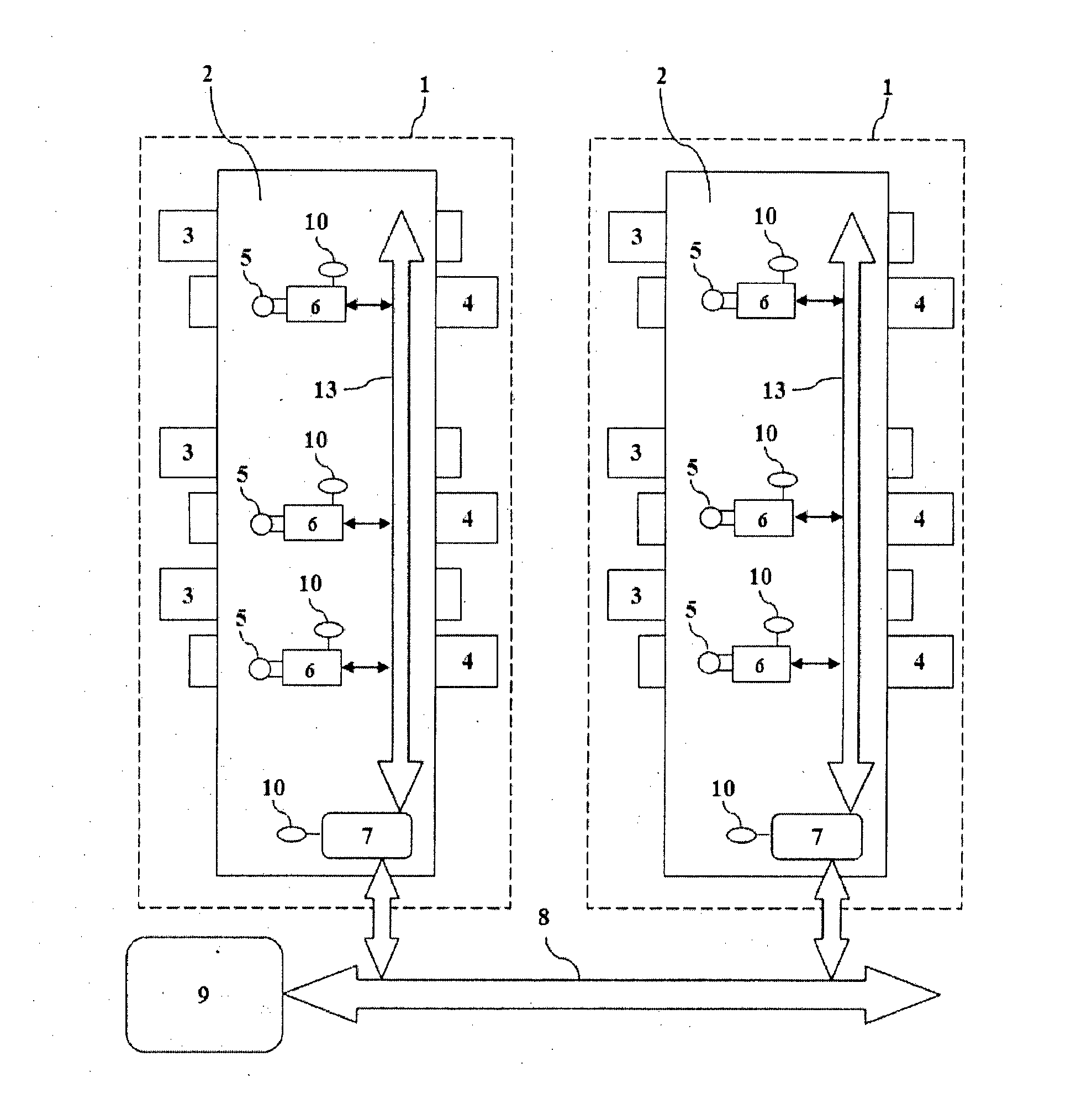
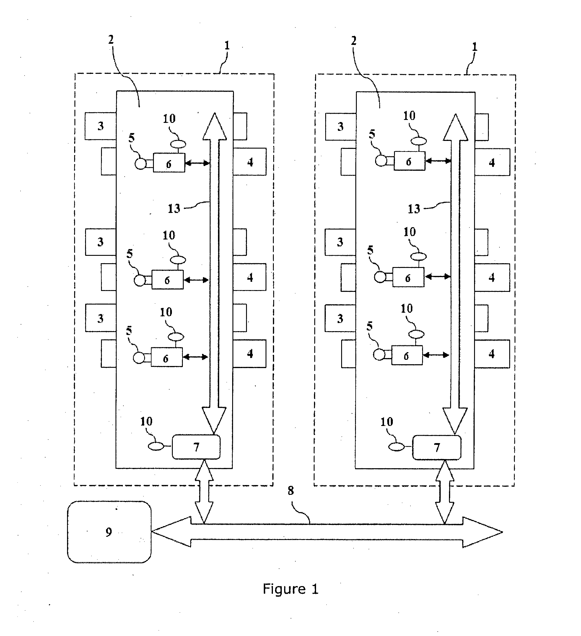
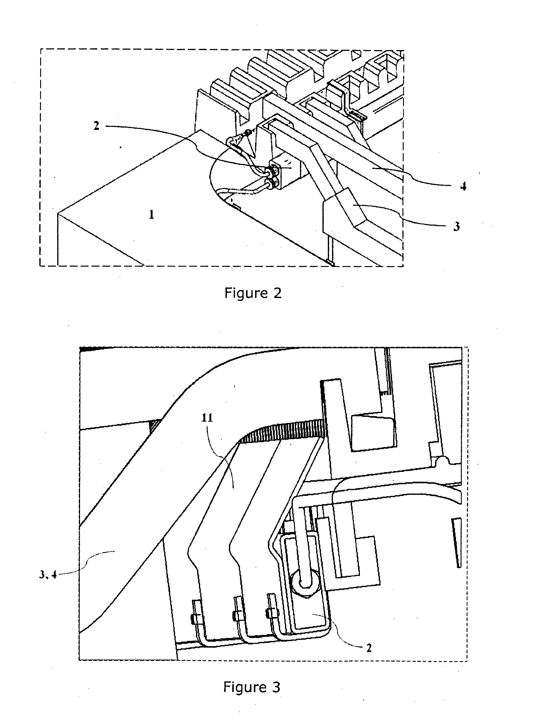
[0059]As shown in FIG. 1, an embodiment of the invention comprises an electrolysis cell (1) comprising a plurality of cathodes (4) and anodes (3) within an electrolyte media, arranged in an alternating manner relative to each other. In the case of the invention, cathodes (4) and anodes (3) correspond to plates which are arranged parallel to each other. In the vicinity of each plate, preferably, of each one of the cathode plates, sensor means (5) are arranged on a sensor bar (2) or ECM bar. Such sensor bar, that is part of the ECM system of the invention, is located in the vicinity of the current bar output (or input) from (or to) the cathode (or anode) plate. Such sensor bar and such sensor means need not be in direct contact with the electrodes. Additionally, the ECM bar (2) may be located in one of many places of the electrolytic cell (1) such as within cell wall, within cell (as shown in FIGS. 2 to 10), within cell top furniture / insulators, attached to electrodes or others. The s...


PUM

PropertyMeasurementUnit
Magnetic fieldaaaaaaaaaa
Electric chargeaaaaaaaaaa
Currentaaaaaaaaaa

Abstract

The present invention relates to an electric current management (ECM) system and method comprising at least one electrolytic cell having at least two electrodes in contact with electrolyte media; a plurality of sensor means for measuring the current passing through one or more electrodes, said sensor means being located inside at least one ECM bar installed in one or more operating electrolytic cells; a support means for supporting at least one ECM bar in each cell; wherein the support means is adapted to avoid disruption to normal electrode movements and damage to the ECM bar. The present invention introduces improvements for minimizing the effects that several types of variables have on current measurement, such as magnetic field interference, cell geometry and contact configuration, in order to provide a reliable approximation of the current passing through each electrode. The present invention can be applied to real time monitoring of each cathode, or anode, constituting a metal electrowinning or electrorefining cell or other electrolytic cell.

Description

FIELD OF APPLICATION[0001]The present invention relates to metallurgical systems, especially electrometallurgical systems, and enhancement of electrolytic cell and / or tankhouse behaviour.[0002]The present invention can be particularly applied to real time monitoring of each cathode, or anode, constituting a metal electrowinning or electrorefining cell or other electrolytic cell with parallel electrodes.BACKGROUND[0003]Metal extraction processes, such as those for copper, often include electrowinning or electrorefining recovery steps. With regard to these steps, it provides an advantage to monitor in real time each metal plate's performance in order to achieve optimum performance of the electrolytic plants.[0004]Within the electrolysis process, a short circuit may occur if electrodes are arranged misaligned; when due to physical flaws metal growth is not uniform on a surface, which may be a result of operational issues such as impurities, higher than acceptable cathode currents, part...

Claims


Application Information

Patent Timeline
IPC IPC(8): C25C7/06C25C1/00
CPCC25C1/00C25C7/06C25B15/02C25D21/12C25D17/004C23F13/04C23F13/22
Inventor BOON, CHRISFRASER, ROBGARCES BARON, JORGEGILL, GERALDJOHNSTON, TIMJOHNSTON, NOELYESBERG, JOHNNOLET, SEBASTIAN
Owner HATCH LTD
Why Eureka
Try Eureka