Light source unit

a technology of light source and light source, which is applied in the direction of lighting and heating apparatus, transportation and packaging, and support devices for lighting, etc., can solve the problems of lower thermal conductivity of materials than of metals, and achieve the effects of reducing weight, increasing assembly work efficiency, and sufficient heat dissipation performan

Active Publication Date: 2015-07-30
KOITO MFG CO LTD
View PDF16 Cites 14 Cited by
  • Summary
  • Abstract
  • Description
  • Claims
  • Application Information

AI Technical Summary

Benefits of technology

[0021]With this configuration, even in the case where the socket and the heat dissipation member are integrated together by inserting the second portion into the through hole, entrance of water or dust into a very small gap between the socket and the second portion can be prevented. As a result, in providing the light source unit that can secure sufficient heat dissipation performance while satisfying such demands as miniaturization and weight reduction, not only can the assembling work efficiency be increased but also the semiconductor light emitting element can be protected from water and dust.

Problems solved by technology

However, in general, such materials are lower in thermal conductivity than metals.

Method used


Image

  • Light source unit
  • Light source unit
  • Light source unit

Examples


Embodiment Construction

[0035]Exemplary embodiments of the invention will be hereinafter described in detail with reference to the accompanying drawings. In the drawings, the scale is changed as appropriate to draw individual members in recognizable sizes. Expressions “front / rear,”“right / left,” and “up / down” are used just for convenience of description and should not be construed as restricting a posture or direction in actual use.

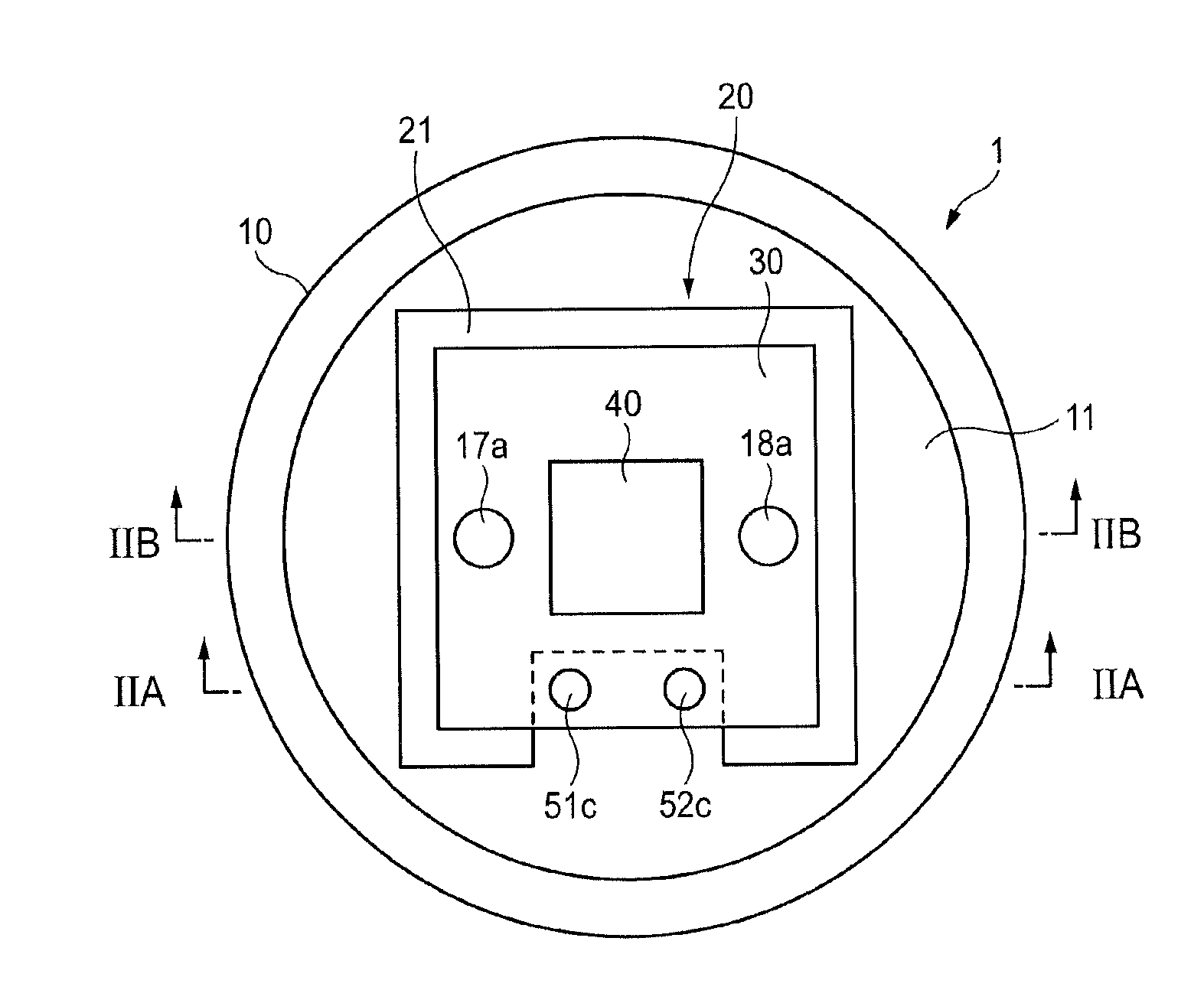
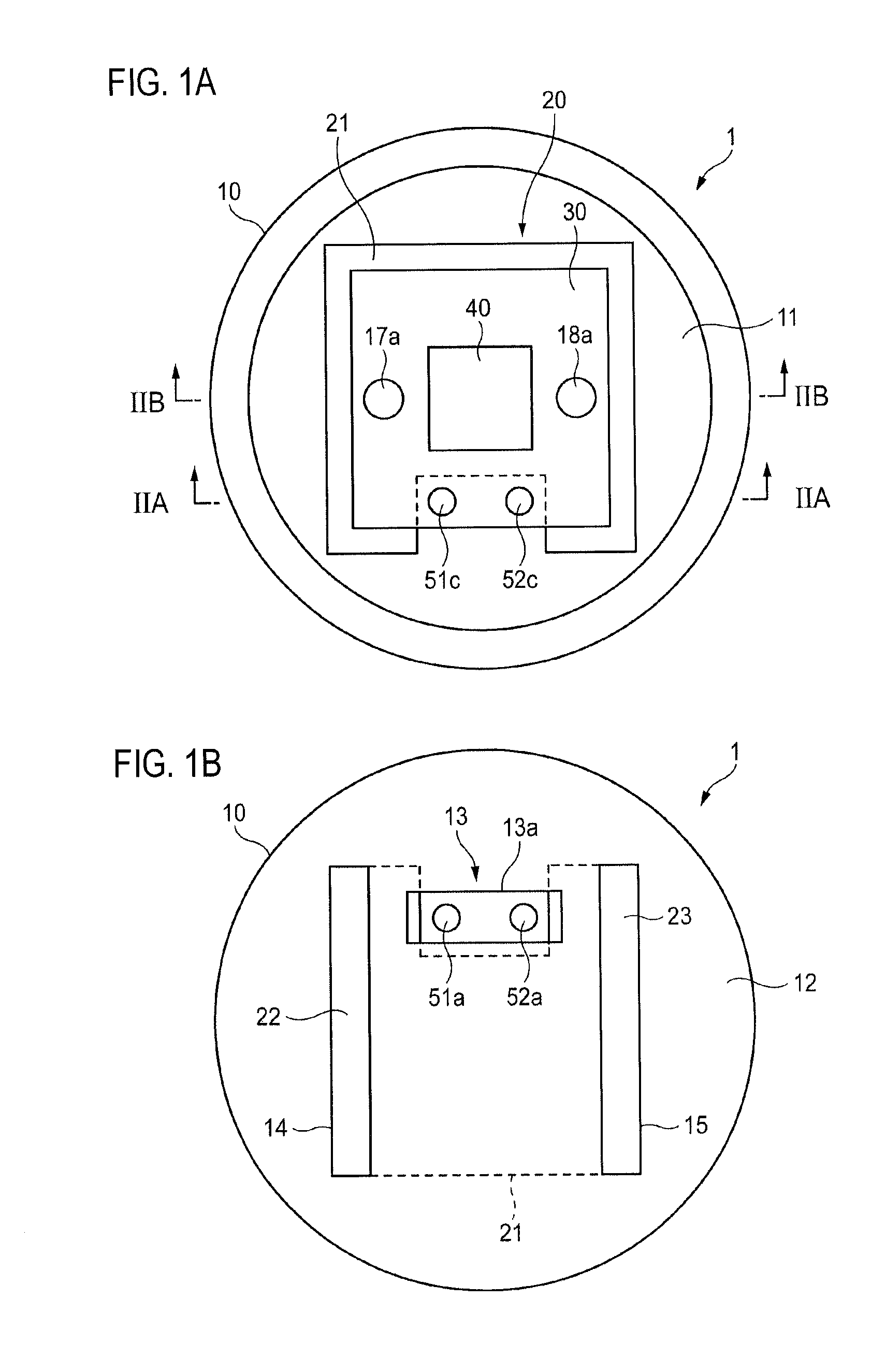
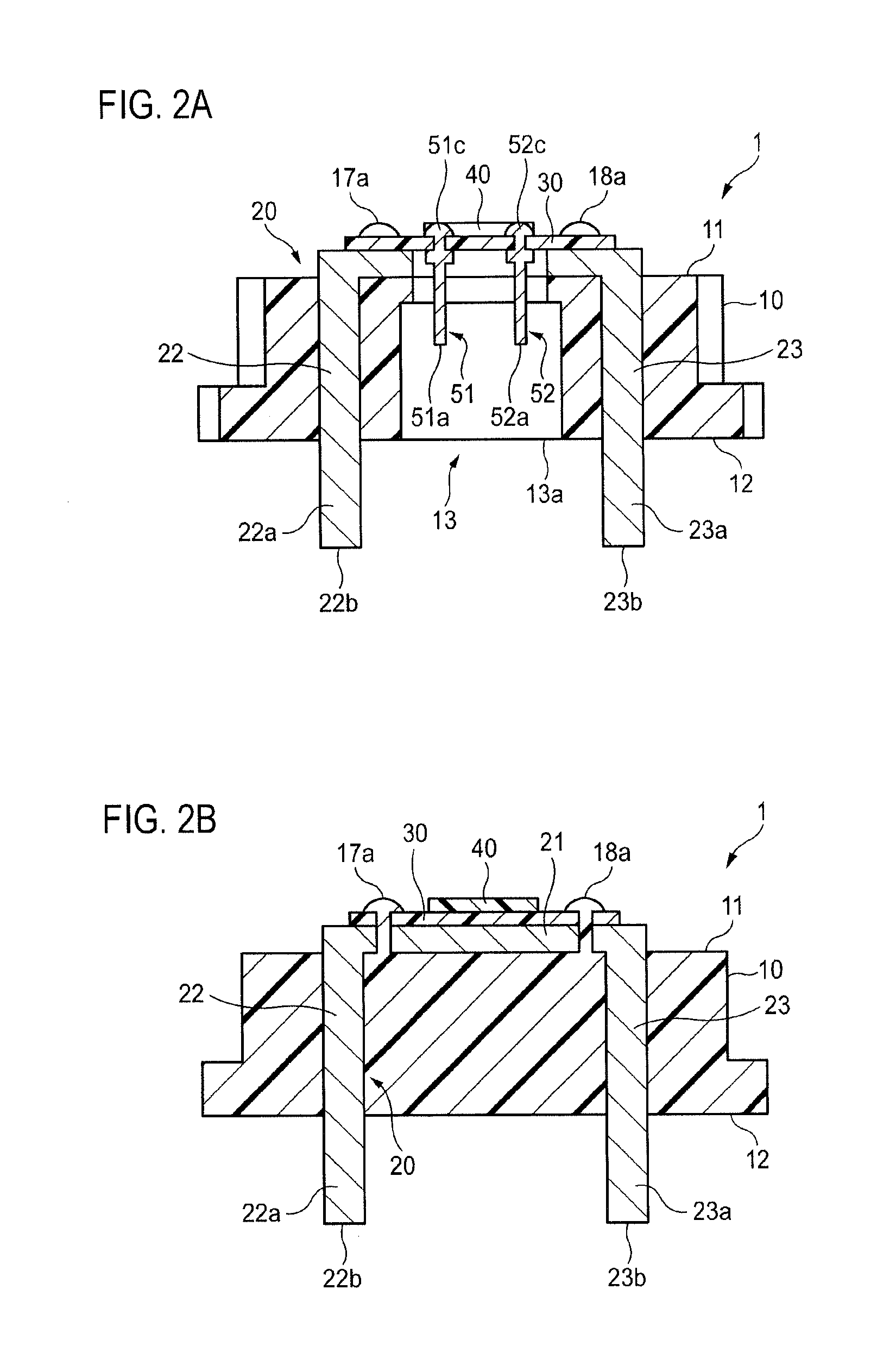
[0036]FIG. 1A is a plan view showing appearances of a light source unit 1 according to a first exemplary embodiment. FIG. 1B is a bottom view showing the appearances of the light source unit 1. FIG. 2A is a sectional views taken along a line IIA-IIA in FIG. 1A and viewed from a directions of an arrow shown in FIG. 1A. FIG. 2B is a sectional views taken along a line IIB-IIB in FIG. 1A and viewed from a directions of an arrow shown in FIG. 1A.

[0037]The light source unit 1 is equipped with a socket 10. The socket 10 has a first surface 11 and a second surface 12. The first surface 1...


PUM


Abstract

A light source unit includes a socket, a heat dissipation member, a board and a semiconductor light emitting element. The socket has a first thermal conductivity and includes a portion that defines a first side and a second side. The heat dissipation member has a second thermal conductivity being higher than the first thermal conductivity. The board is disposed on the first side. The semiconductor light emitting element is supported by the board. The socket is an injection-molded member. The heat dissipation member includes a first portion and a second portion. The first portion is disposed on the first side, extends in a first direction, and supports the board. The second portion includes a portion extending in a second direction intersecting with the first direction, as a result of being subjected to bending processing. A part of the second portion is disposed on the second side.

Description

CROSS REFERENCE TO RELATED APPLICATION(S)[0001]This application is based on and claims priority under 35 U.S.C. §119 to Japanese Patent Application Nos. 2014-013132 (filed on Jan. 28, 2014) and 2014-243036 (filed on Dec. 1, 2014), the entire contents of which are incorporated herein by reference.BACKGROUND[0002]1. Technical Field[0003]Exemplary embodiments of the invention relate to a light source unit to be incorporated in an illumination device which is to be mounted in a vehicle.[0004]2. Related Art[0005]For example, JP 2012-119243 A describes a light source unit to be incorporated in an illumination device which is to be mounted in a vehicle. This light source unit employs a semiconductor light emitting element as a light source. To dissipate heat that is generated in association with light emission, a board that supports the semiconductor light emitting element is fixed on a heat dissipation member.SUMMARY[0006]One exemplary of the invention secure a sufficient level of heat di...

Claims


Application Information

Patent Timeline
Patent Type & Authority Applications(United States)
IPC IPC(8): F21V29/74F21V23/00F21V23/06F21W107/10
CPCF21V29/74F21Y2101/02F21V23/005F21V23/06F21V17/00F21V31/00F21S43/00F21W2107/10F21S41/143F21S41/192F21S41/194F21S41/285F21S41/321F21S45/30F21S45/47F21S45/49
Inventor IKUTA, RYUJIROOTSUBO, TAKAYUKIOZAWA, ATSUSHISERITA, TAKUYA
Owner KOITO MFG CO LTD
Why Eureka
Try Eureka