
Ultrasonic device, probe, electronic device, and ultrasound imaging apparatus

a technology of ultrasound imaging and ultrasonic devices, applied in the direction of mechanical vibration separation, instruments, applications, etc., can solve the problems of resin material not being able to adequately spread into the corners of the space, the inability to obtain clear ultrasound images, etc., to achieve the effect of preventing the crushing of the acoustic matching layer, preventing and adequately suppressing the deformation of the acoustic lens

Inactive Publication Date: 2015-08-06
SEIKO EPSON CORP
View PDF8 Cites 7 Cited by
  • Summary
  • Abstract
  • Description
  • Claims
  • Application Information

AI Technical Summary

Benefits of technology

The patent text describes an ultrasonic transducer that can be pressed against a living body without deforming the acoustic lens. The use of a single acoustic matching layer simplifies the formation process and allows for precise control of the film thickness. The technical effect of this invention is improved ultrasonic imaging.

Problems solved by technology

A clear ultrasound image cannot be obtained.
On the other hand, when dripped resin material is pressed to spread out by another part and the resin material fills the space, the resin material cannot adequately spread into the corners in the space.

Method used


Image

  • Ultrasonic device, probe, electronic device, and ultrasound imaging apparatus
  • Ultrasonic device, probe, electronic device, and ultrasound imaging apparatus
  • Ultrasonic device, probe, electronic device, and ultrasound imaging apparatus

Examples


Embodiment Construction

[0046]An embodiment of the present invention is explained with reference to the attached drawings. The embodiment explained below does not unreasonably limit the content of the present invention described in the scope of the patent claims, and does not limit any of the structures described in this embodiment that are essential as means for solving the present invention.

(1) Overall Configuration of Ultrasound Imaging Apparatus

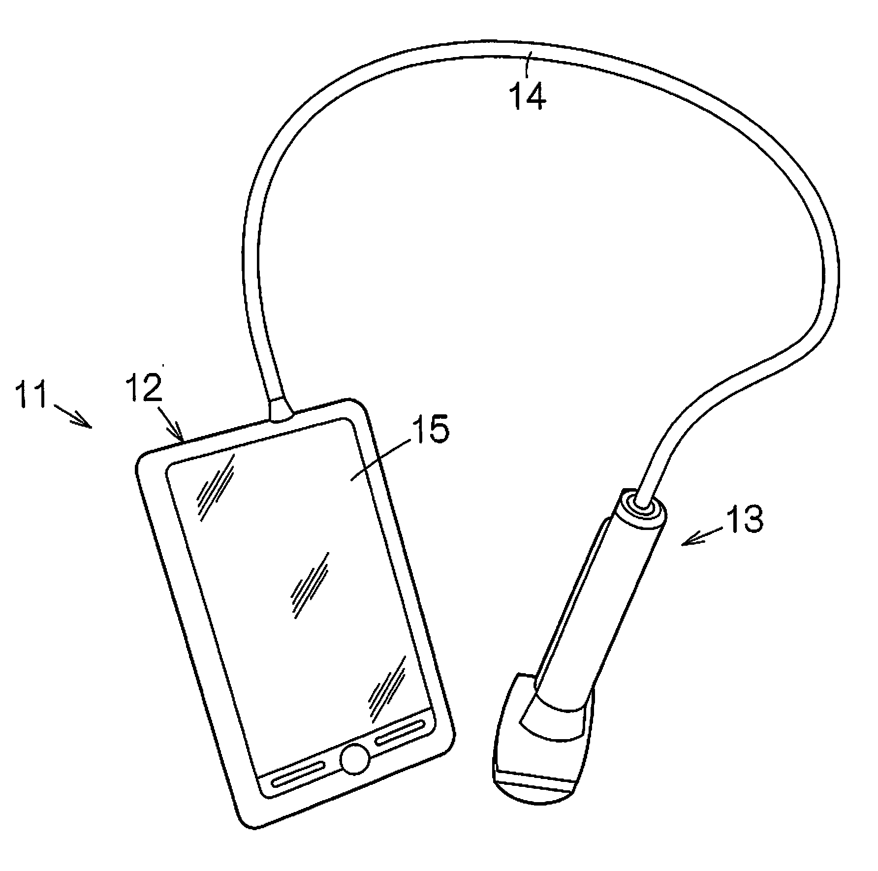
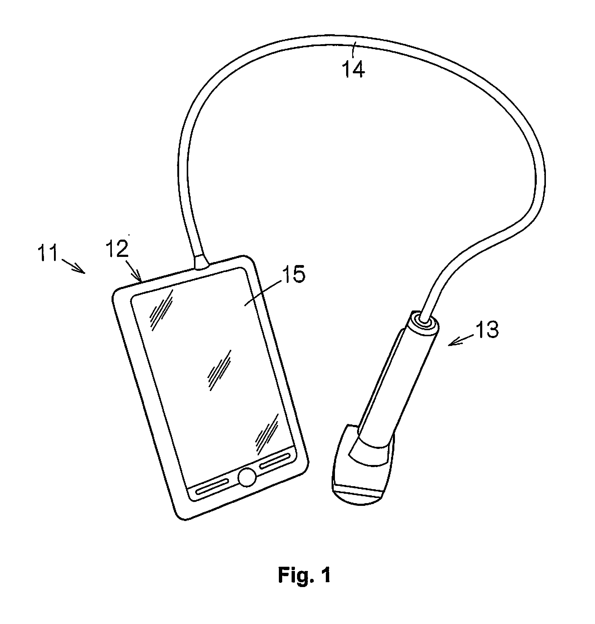
[0047]FIG. 1 schematically shows an example of an electronic device related to one embodiment of the present invention, namely the configuration of an ultrasound diagnostic apparatus (ultrasound imaging apparatus) 11. The ultrasound diagnostic apparatus 11 is provided with an apparatus terminal (processing unit) 12 and an ultrasonic probe (probe) 13. The apparatus terminal 12 and the ultrasonic probe 13 are connected to each other by a cable 14. The apparatus terminal 12 and the ultrasonic probe 13 exchange electrical signals through the cable 14. A display pane...


PUM

PropertyMeasurementUnit
thicknessaaaaaaaaaa
compressive strengthaaaaaaaaaa

Abstract

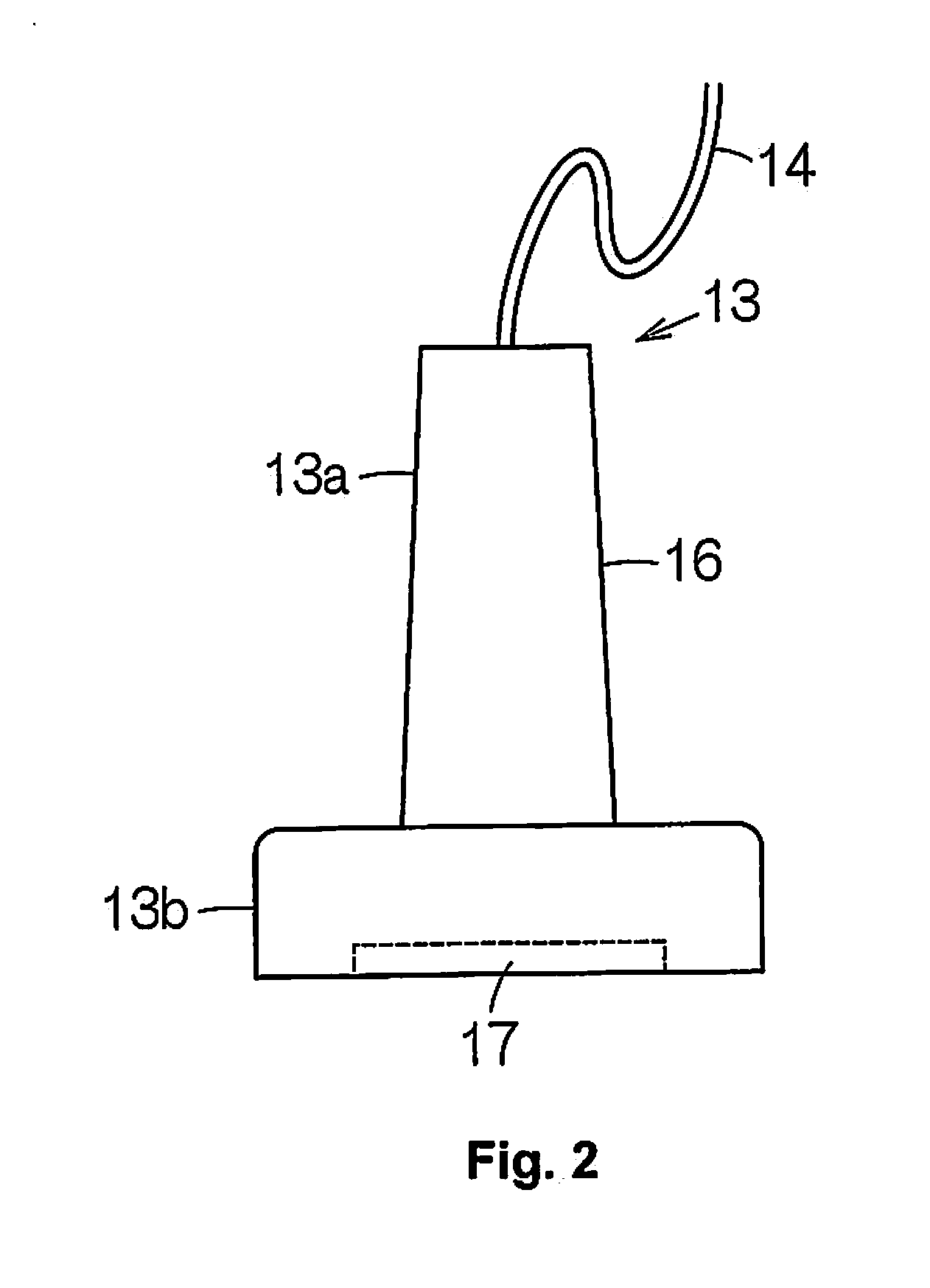
An ultrasonic device includes a substrate, an acoustic matching layer, an acoustic lens, and a structure. The substrate has an element array including a plurality of thin-film ultrasonic transducer elements arranged in an array form. The acoustic matching layer covers the element array. The acoustic lens is arranged on the acoustic matching layer. The structure is arranged between the acoustic lens and the substrate and has a larger compressive strength than a compressive strength of the acoustic matching layer.

Description

CROSS-REFERENCE TO RELATED APPLICATIONS[0001]This application claims priority to Japanese Patent Application No. 2014-016639 filed on Jan. 31, 2014. The entire disclosure of Japanese Patent Application No. 2014-016639 is hereby incorporated herein by reference.BACKGROUND[0002]1. Technical Field[0003]The present invention relates to an ultrasonic device, and a probe, an electronic device, and an ultrasound imaging apparatus that use the same.[0004]2. Related Art[0005]As disclosed in Japanese Laid-Open Patent Publication No. 2008-193357, an ultrasound diagnostic apparatus called an ultrasound imaging apparatus is commonly known. An ultrasound imaging apparatus is provided with a plurality of ultrasonic transducer elements arranged in an array form. The ultrasonic transducer elements are formed from so-called capacitive micromachined ultrasonic transducers (cMUTs; electrostatic capacitive type). An acoustic lens covers the array of ultrasonic transducer elements. The acoustic lens is a...

Claims


Application Information

Patent Timeline
Patent Type & Authority Applications(United States)
IPC IPC(8): A61B8/00B06B1/06B32B38/00B32B37/24B32B37/06G10K11/30A61B8/08
CPCA61B8/4427B06B1/0622B32B2457/08B32B2398/00B32B2310/0806B32B2307/10B32B2038/0076B32B38/0008B32B37/24B32B37/06B06B1/064A61B8/5207A61B8/461A61B8/4494A61B8/4444B32B2535/00G10K11/30B06B1/0629B06B1/067
Inventor KIYOSE, KANECHIKA
Owner SEIKO EPSON CORP
Learn More