
Vibrating screen

a technology of vibrating screen and frame, which is applied in the direction of filtration separation, borehole/well accessories, separation processes, etc., can solve the problems of increasing the load and stress on the other components of the apparatus, increasing the mass of the frame, increasing the vibration force that must be generated, and increasing the weight of the frame. , to achieve the effect of greatly facilitating assembly and manufacture of the apparatus

Active Publication Date: 2015-08-06
CDE GLOBAL
View PDF6 Cites 10 Cited by
  • Summary
  • Abstract
  • Description
  • Claims
  • Application Information

AI Technical Summary

Benefits of technology

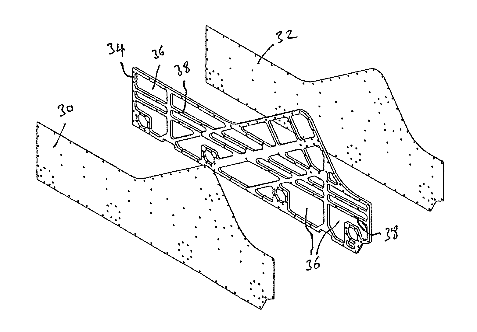
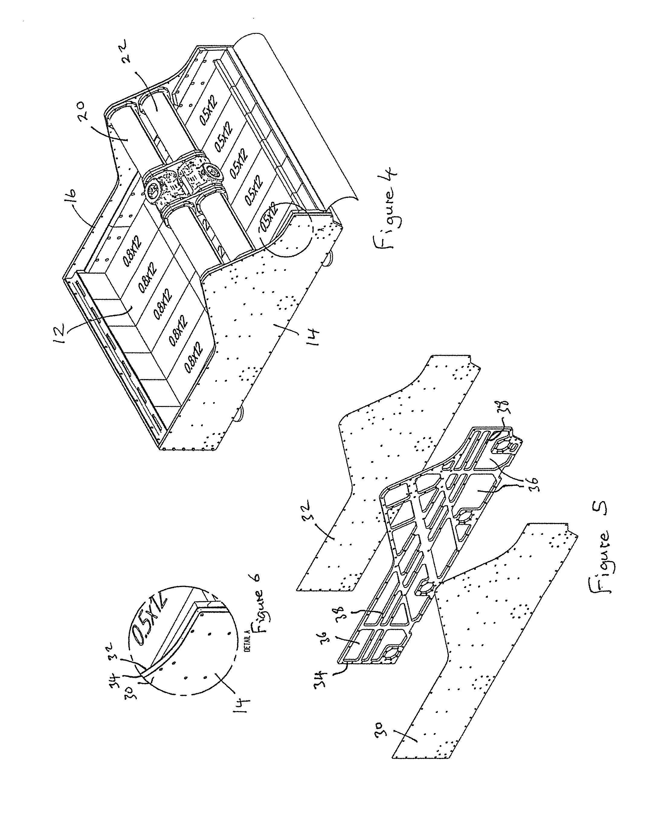
The invention relates to an intermediate member used in a frame for vehicles. This member has a pattern of apertures and cut-outs that define a peripheral border region and reinforcing members. This pattern of reinforcing members adds stiffness and strength to the frame's side walls while minimizing the weight. The invention also avoids heat-related problems associated with welded structures and simplifies assembly and manufacture of the frame.

Problems solved by technology

However, increasing the strength of the frame, for example by increasing the thickness of the material from which the frame is made, also typically results in a corresponding increase in the weight of the frame, resulting in an increase in the stresses to which the frame is exposed and also increasing the load and stresses on the other components of the apparatus, in particular upon the base upon which the frame is supported.
In addition, increasing the mass of the frame increases the vibration forces that must be generated by the rotors to achieve the required motion of the deck.
Previous attempts to increase the strength of the frame without substantially increasing its weight have resulted in complex structures that are time consuming and costly to manufacture.

Method used


Image

  • Vibrating screen
  • Vibrating screen
  • Vibrating screen

Examples


Embodiment Construction

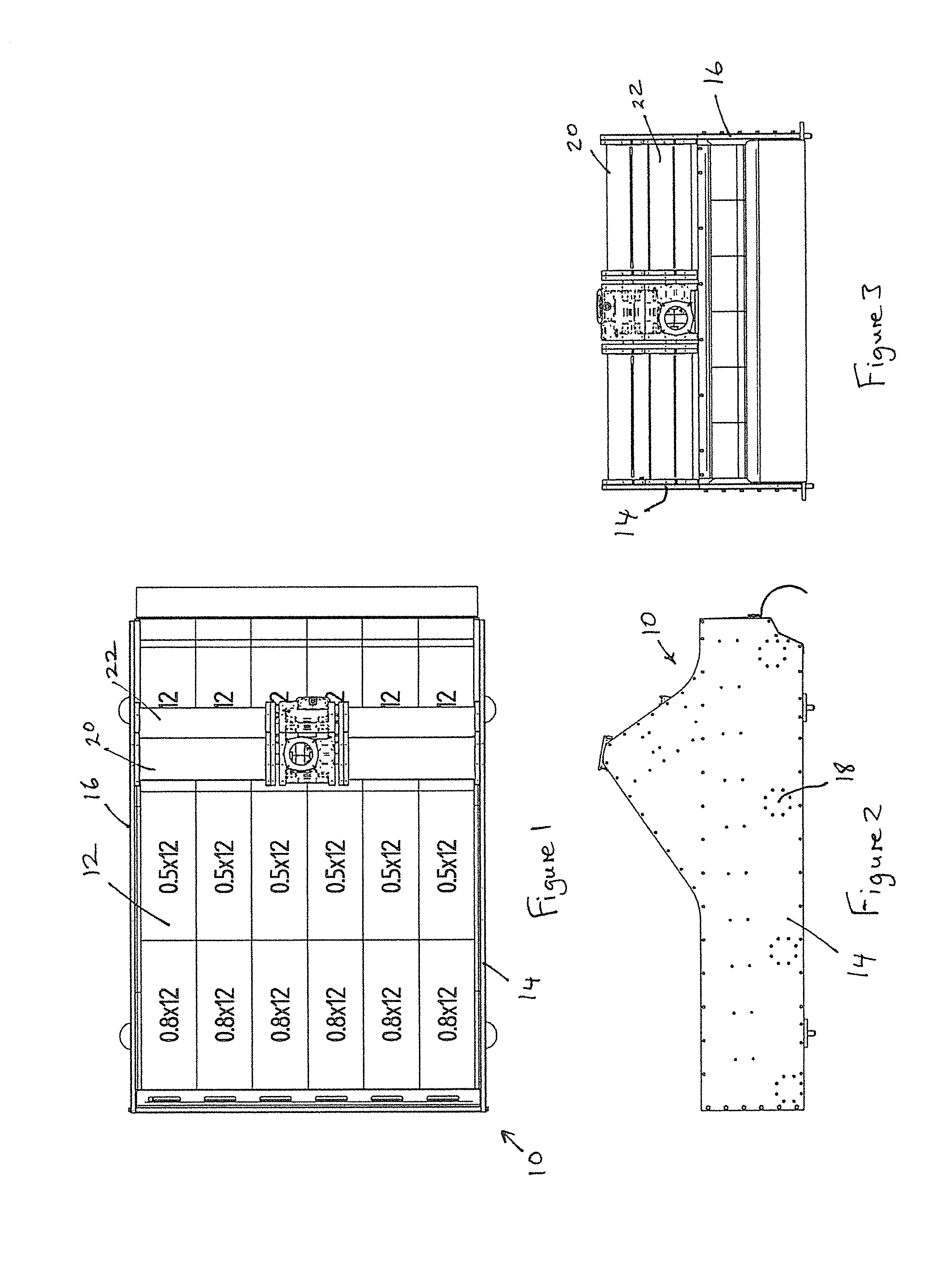
[0024]A dewatering screen in accordance with a first embodiment of the present invention is illustrated in FIGS. 1 to 6. The dewatering screen 10 comprises a modular polyurethane deck 12 having a plurality of small slots formed therein (of approximately 0.5 to 0.8 mm width). The deck 12 is mounted on a support frame comprises spaced apart side walls 14,16 joined by transversely extending bridging members 18. The support frame may be mounted on a base frame (not shown) via resilient mountings to allow the support frame to move with respect to the base frame. The support frame may be suspended from the base frame via suitable resilient mounts, such as springs.

[0025]A vibration generating means is mounted between the side plates 14,16 of the support frame, extending transverse to the deck 12 of the dewatering screen 10. The vibration generating means may comprise a pair of motor driven eccentrically loaded rotors mounted in or on support pipes 20,22 mounted between the side plates 14,1...


PUM

PropertyMeasurementUnit
Fractionaaaaaaaaaa
Fractionaaaaaaaaaa
Surface areaaaaaaaaaaa

Abstract

A vibrating screen is provided for separating excess water from particulate materials such as sand, gravel, iron ore, sludge or other particulate material and / or for grading, classifying or sorting particulate material by size. The vibrating screen includes a frame upon which is mounted a deck having a plurality of apertures therein, the frame being mounted on a base and being provided with vibration generating means for imparting vibration to the deck, wherein the frame includes pair of substantially parallel side walls between which the screen is mounted, each side wall including a pair of spaced apart side members defining outer faces of the side wall, at least one intermediate member being located between the side members, wherein the at least one intermediate member incorporates a plurality of apertures and / or cut-outs therethrough.

Description

FIELD OF THE INVENTION[0001]This invention relates to a vibrating screen and in particular to a vibrating screen for separating excess water from particulate material, such as sand, gravel, iron ore, sludge or other particulate material and / or for grading, classifying or sorting particulate material by size.BACKGROUND OF THE INVENTION[0002]Vibrating screens are commonly used to separate excess water from particulate materials, for example in sand quarrying to remove excess water from sand following grading and / or washing processes, and are used to sort, grade or classify particulate material, such as sand.[0003]A typical vibrating screen comprises a frame, defied by a pair of substantially parallel side walls interconnected by transversely extending bridging members, upon which is mounted a substantially horizontal polyurethane deck having small openings or slots for water and / undersize particles to pass through. The deck is vibrated at high frequency to shake out excess water and / o...

Claims


Application Information

Patent Timeline
IPC IPC(8): B01D35/20B07B1/46B07B1/28
CPCB07B1/28B32B15/011B07B1/46B07B2201/00B01D35/20B07B2230/01B32B15/01B03B4/00B03B4/02B07B1/40B01D33/03B32B15/00B01D33/0376E21B21/065
Inventor CONVERY, ANTHONY
Owner CDE GLOBAL
Learn More