Apparatus and method for assessing thermo-mechanical fatigue related phenomena within a test material

a technology of thermomechanical fatigue and test material, which is applied in the direction of material flaw investigation, measurement devices, instruments, etc., can solve the problems of not giving sufficient details to include, and not excluding the possibility of additional non-isothermal effects that might further accelerate the crack, so as to achieve simple and cost-effective effects

Active Publication Date: 2015-08-06
FRACTURELAB
View PDF9 Cites 7 Cited by
  • Summary
  • Abstract
  • Description
  • Claims
  • Application Information

AI Technical Summary

Benefits of technology

[0049]As can be seen, many other useful embodiments could be devised by one skilled in the art to enable testing to evaluate a wide variety of thermo-mechanical phenomena, including but not limited to thermo-mechanically induced creep, residual stress, changes in physical properties, crack initiation or crack growth in a relatively simple and cost-effective manner.

Problems solved by technology

Insensitivity to thickness allows reliable comparison between different specimen configurations, and is often accompanied by insensitivity to cooling methods, but in current practice is only available in the short pulse mode.
They did not give sufficient details to include the component and 4-point bend tests in the table, but they were run with a 0.8 ms heat pulse on various items.
While the material characterization and analysis method can account for quite general hot-compressive time-dependent behavior in a variable-temperature environment, the partial validation performed utilized an isothermal test method that, while capturing the isothermal creep-related phenomena, could not rule out the possibility of additional non-isothermal effects that might further accelerate the crack.

Method used


Image

  • Apparatus and method for assessing thermo-mechanical fatigue related phenomena within a test material
  • Apparatus and method for assessing thermo-mechanical fatigue related phenomena within a test material
  • Apparatus and method for assessing thermo-mechanical fatigue related phenomena within a test material

Examples


Embodiment Construction

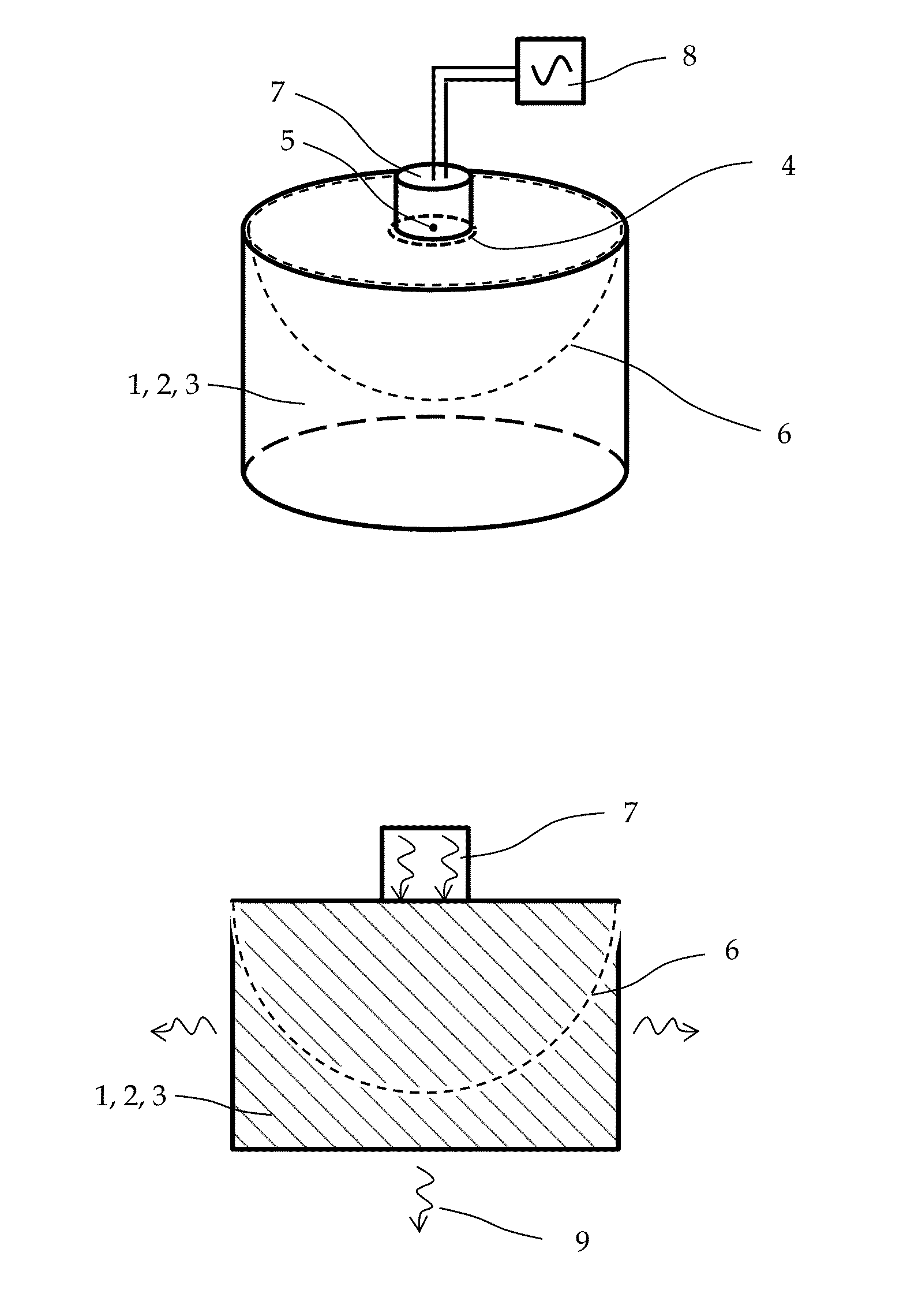
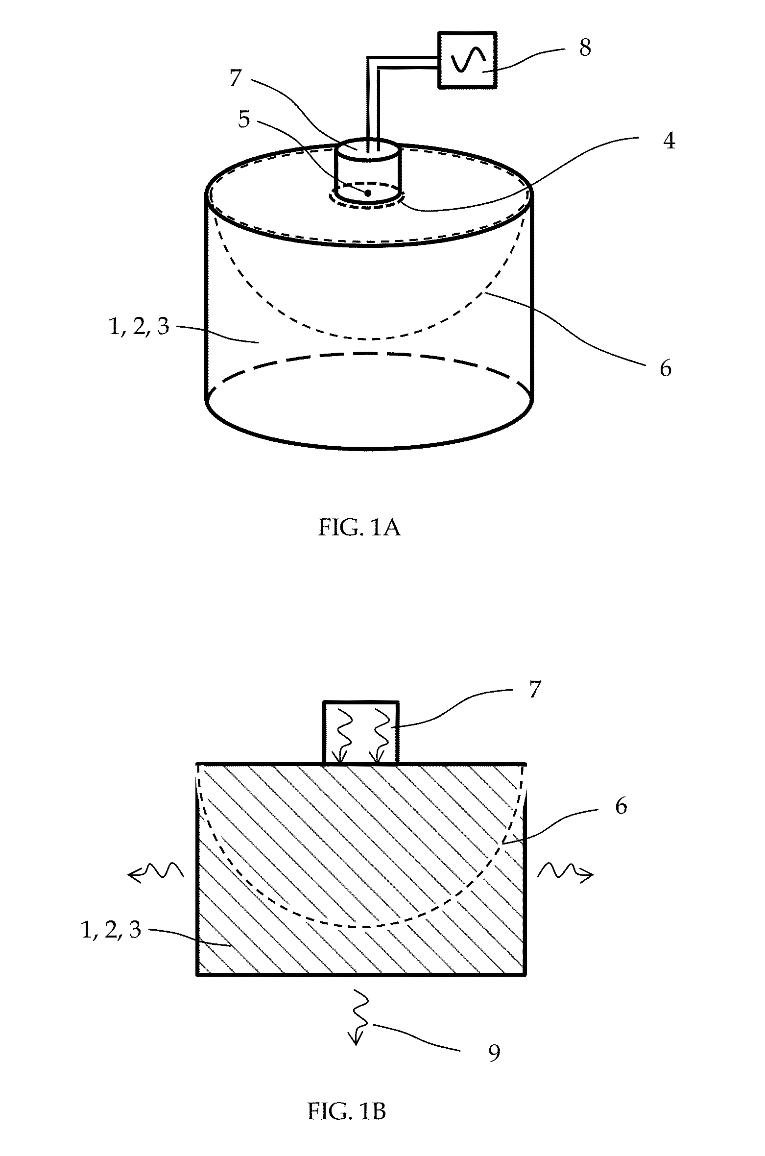
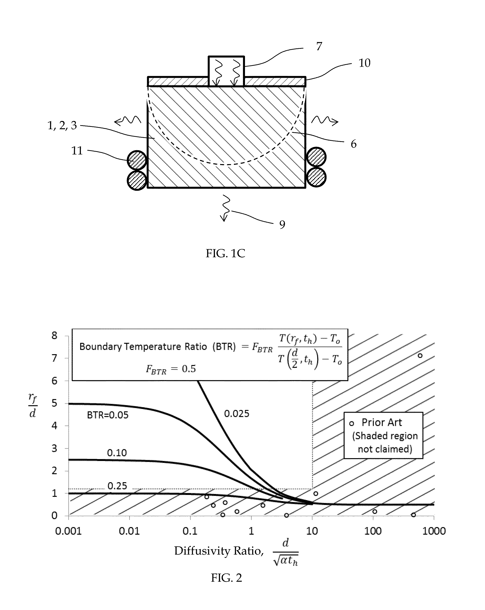
[0059]FIGS. 1A, 1B, and 1C show a schematic representation of a test apparatus for assessing thermo-mechanical fatigue related phenomena within a test material 1, FIGS. 1B and 1C being cross-sectional views with additional detail, and FIG. 1C illustrating additional features not shown in FIGS. 1A and 1B. The embodiment utilizes a test specimen 2 prepared of a body 3 of test material 1, with a primary heat introduction zone 4 consisting of a portion of the surface of said body 3, of a size characterized by its maximum dimension, and having a centroid 5. The size and shape of the body 3 is configured to substantially include a hemispherical region 6, described earlier as the fiducial hemisphere, of said test material 1 centered upon the centroid 5. For reasons already described, the ratio of the radius of the fiducial hemisphere 6 to the maximum dimension of the primary heat introduction zone 4 is configured to be greater than or equal to 1.2 to provide basic utility.

[0060]The embodim...


PUM

PropertyMeasurementUnit
porosityaaaaaaaaaa
sizeaaaaaaaaaa
thermo-mechanical fatigueaaaaaaaaaa

Abstract

The invention pertains to a test apparatus and method for assessing thermo-mechanical fatigue related phenomena within a test material wherein a heat source, such as a laser beam is applied to a specimen consisting of a body of the test material, thereby introducing heat to a primary heat introduction zone on the surface of the body to cause local cyclic heating. As part of the cycle, heat is removed through a portion of the specimen surface sufficiently remote from the heat introduction zone to create a substantially spherical temperature gradient within the specimen resembling that of a point source on a semi-infinite body. A stress gradient results from local thermal expansion, thus thermo-mechanically cycling the material. As a result of the thermo-mechanical cycling, phenomena including thermo-mechanically induced creep, residual stress, changes in physical properties, crack initiation and crack growth may be observed within the material, and evaluated for scientific or engineering purposes. An optional background temperature control feature may also be included to raise the background temperature of the specimen during thermal cycling. Among many useful embodiments described herein, the test method may also be configured for non-destructive use on a component, wherein the local damage or crack growth due to thermal cycling is afterwards removed and the surface blended or otherwise reconditioned as required to restore component functionality and structural integrity.

Description

CROSS-REFERENCE TO RELATED APPLICATIONS[0001]Not Applicable.BACKGROUND OF THE INVENTION[0002]1. Field of the Invention[0003]The invention pertains to a test apparatus and method for assessing thermo-mechanical fatigue related phenomena within a test material, including but not limited to thermo-mechanically induced creep, residual stress, changes in physical properties, crack initiation and crack growth, occurring at temperatures below the melting temperature of the material.[0004]2. Description of the Prior Art[0005]Thermo-mechanical fatigue (TMF) testing is necessary in elevated temperature engineering applications where component durability and safety concerns merit the associated costs, which are often substantial, due to the difficulty of cycling both thermally and mechanically at the same time. A well-known type of TMF test is performed on a tubular specimen intermittently induction heated and cooled by air running through the tube, while simultaneously being loaded mechanical...

Claims


Application Information

Patent Timeline
Patent Type & Authority Applications(United States)
IPC IPC(8): G01N25/72
CPCG01N25/72
Inventor PETTIT, RICHARD G.
Owner FRACTURELAB
Why Eureka
Try Eureka