Superalloy solid freeform fabrication and repair with preforms of metal and flux

a technology of flux and superalloys, applied in the direction of manufacturing tools, machines/engines, and so on, can solve the problems of inability to weld with traditional processes, limited hot box welding, and inability to meet the requirements of many repair applications

Inactive Publication Date: 2015-08-13
SIEMENS ENERGY INC
View PDF4 Cites 61 Cited by
  • Summary
  • Abstract
  • Description
  • Claims
  • Application Information

AI Technical Summary

Problems solved by technology

However, hot box welding is limited by the difficulty of maintaining a uniform component process surface temperature and the difficulty of maintaining complete inert gas shielding, and by physical difficulties imposed on the operator working in the proximity of a component at high temperatures.
However, this technique is not practical for many repair applications where the geometry of the parts does not facilitate the use of a chill plate.
Alloys outside the zone of weldability are recognized as being very difficult or impossible to weld with traditional processes, and the alloys with the highest aluminum content are generally found to be the most difficult to weld, as indicated by the arrow.
However, versions of SLM have had some or all of the following disadvantages:a) Limited to processing on a flat horizontal surface in a chamber in order to retain the powder by gravity during laser processingb) Limited to weldable materials such as shown in FIG. 1.c) A slow process, because each layer must be thin, such as 20 microns.
Various versions of laser cladding have had some or all of the following disadvantages:a) Slow process because each layer must be thin, such as 0.5 mm.b) Even slower for materials that are hard to weld as shown in FIG. 1c) Requires an inert shielding gas to avoid oxidationd) Requires high preheating or fast cooling of the substrate to avoid crackinge) In some cases there is sensitivity to the powder production method
This constitutes a limitation on each of these processes for SFF of superalloys, both in terms of optimization of laser coupling and in customization of particle sizes for other reasons.

Method used


Image

  • Superalloy solid freeform fabrication and repair with preforms of metal and flux
  • Superalloy solid freeform fabrication and repair with preforms of metal and flux
  • Superalloy solid freeform fabrication and repair with preforms of metal and flux

Examples


Embodiment Construction

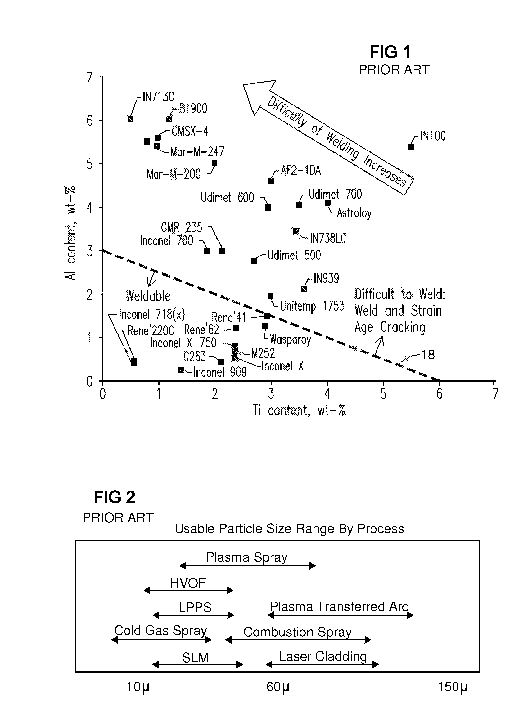
[0044]The present inventors developed a process and apparatus for solid freeform fabrication and repair having the following advantages:[0045]a) Can build on existing 3-D surfaces Not limited to horizontal flat surfaces[0046]b) High build rate, such as over 3 or 4 mm per layer[0047]c) Usable for metals that are difficult to weld[0048]d) Robust process that is adaptable to new damage modes.[0049]e) No pre-heating or fast cooling needed.[0050]f) No shielding of the melt pool by inert gas is needed[0051]g) Wide range of powder sizes.[0052]h) Reduced sensitivity to the powder production method.

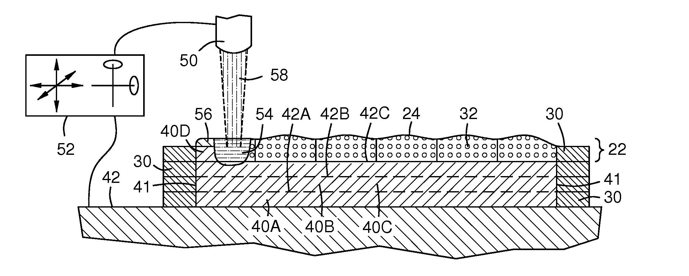
[0053]An embodiment of the invention includes the steps described here. A preform of metal powder and flux powder is created that contains metal to be added to a component being additively fabricated or repaired The metal in the preform may be constrained in a distribution that defines a shape of a layer or slice of the component. The preform is preplaced on a working surface such as a work table,...


PUM

PropertyMeasurementUnit
open porosityaaaaaaaaaa
thickaaaaaaaaaa
temperatureaaaaaaaaaa

Abstract

A preform (22, 22A-U) containing metal (32, 34) and flux (33) for forming a metal layer to be added to a component being repaired or additively manufactured. The metal may be constrained in the preform in a distribution that forms a shape of a sectional layer or a surface repair of a component in response to an energy beam (58) that melts the preform. The preform is placed on a working surface (42), which may be a previously formed layer (42A-C) in additive manufacturing, or may be an existing component surface (122) for repair The preform is then melted by the energy beam (58) to form a new integrated layer (40A-F) on the component with an over-layer of slag (56) that shields and insulates the melt pool (54) and the solidifying layer The slag is removed, and a subsequent layer may be added.

Description

FIELD OF THE INVENTION[0001]This invention relates generally to the field of solid freeform fabrication and repair of metal components, and particularly to additive layer fabrication and repair of high-temperature superalloy componentsBACKGROUND OF THE INVENTION[0002]Industry is increasingly using Solid Freefrom Fabrication (SFF) technologies to produce fully functional metal parts. This family of additive manufacturing processes involves layer-wise accumulation and consolidation of material (e.g. powder and wire), allowing parts to be produced with a high geometric freedom directly from a CAD model. A group of SFF technologies known as direct metal laser fabrication (DMLF) utilizes lasers to consolidate powder. Other groups use tungsten inert gas (TIG), Metal inert gas (MIG), or electron beam technologies.[0003]Additive manufacturing enables a component to be fabricated by building it in layers. Each layer is melted, sintered, or otherwise integrated onto a previous layer. Each lay...

Claims


Application Information

Patent Timeline
Patent Type & Authority Applications(United States)
IPC IPC(8): B23P6/00B23K26/00B22F3/105B23K25/00B23K35/02B23K35/36
CPCB23P6/002B23K35/0255B23K35/36B33Y80/00B23K25/005B23K26/0012B33Y10/00B22F3/105B23P6/007F01D5/005B23K26/342B23K2101/001B23K2103/08B23K2103/26
Inventor BRUCK, GERALD J.KAMEL, AHMEDJOUINI, DHAFER
Owner SIEMENS ENERGY INC
Why Eureka
Try Eureka