Computer Controlled UV LED Curing Apparatus

a technology of uv led and curing apparatus, which is applied in the field of curing methods and apparatuses for photosensitive materials, can solve the problems of mercury bulb life span, mercury bulb deformation during its lifetime, and relatively short life of mercury bulb used in mercury-arc lamps, and achieves the effect of enhancing uniform distribution and application of uv light and high intensity

Inactive Publication Date: 2015-08-13
OTHONIA CURING TECH APS
View PDF12 Cites 8 Cited by
  • Summary
  • Abstract
  • Description
  • Claims
  • Application Information

AI Technical Summary

Benefits of technology

[0020]The method and apparatus of the present invention provide substantially uniform continuous or intermittent blasts or pulses of high intensity UV light are emitted from UV light emitters in one or more UV curing apparatus at a substantially constant output level and intensity along one or more UV light paths.
[0021]The UV light emitters are super high power UV-LED modules with high intensity UV-LED chips. Significantly, the high intensity UV-LED chips are prevented from being positioned opposite each other and in the path of the high intensity UV light so that the high intensity UV light does not contact and degrade the high intensity UV-LED chips. The UV curable products, articles, inks, coatings, adhesives, and other objects can be intermittently, sequentially or continuously positioned in the UV light path. Desirably, the UV light is substantially uniformly applied and distributed on the UV curable products, articles, inks, coatings, adhesives, and other prod

Problems solved by technology

The most obvious disadvantage is the life span of the mercury bulbs used in the mercury-arc lamps.
Mercury bulbs have a relatively short life, typically 100-1000 hours.
Further, the mercury bulb degrades nonlinearly during its lifetime.
As a result, conventional mercury-arc photocuring systems often require means to monitor and adjust the output power as the mercury bulb degrades.
Further, mercury-arc lamps are typically powered on even during stand-by periods because they require cumbersome warm-up and cool-down cycles; as a result, much of the life of the mercury bulbs may be lost during these stand-by periods.
Another disa

Method used


Image

  • Computer Controlled UV LED Curing Apparatus
  • Computer Controlled UV LED Curing Apparatus
  • Computer Controlled UV LED Curing Apparatus

Examples


Embodiment Construction

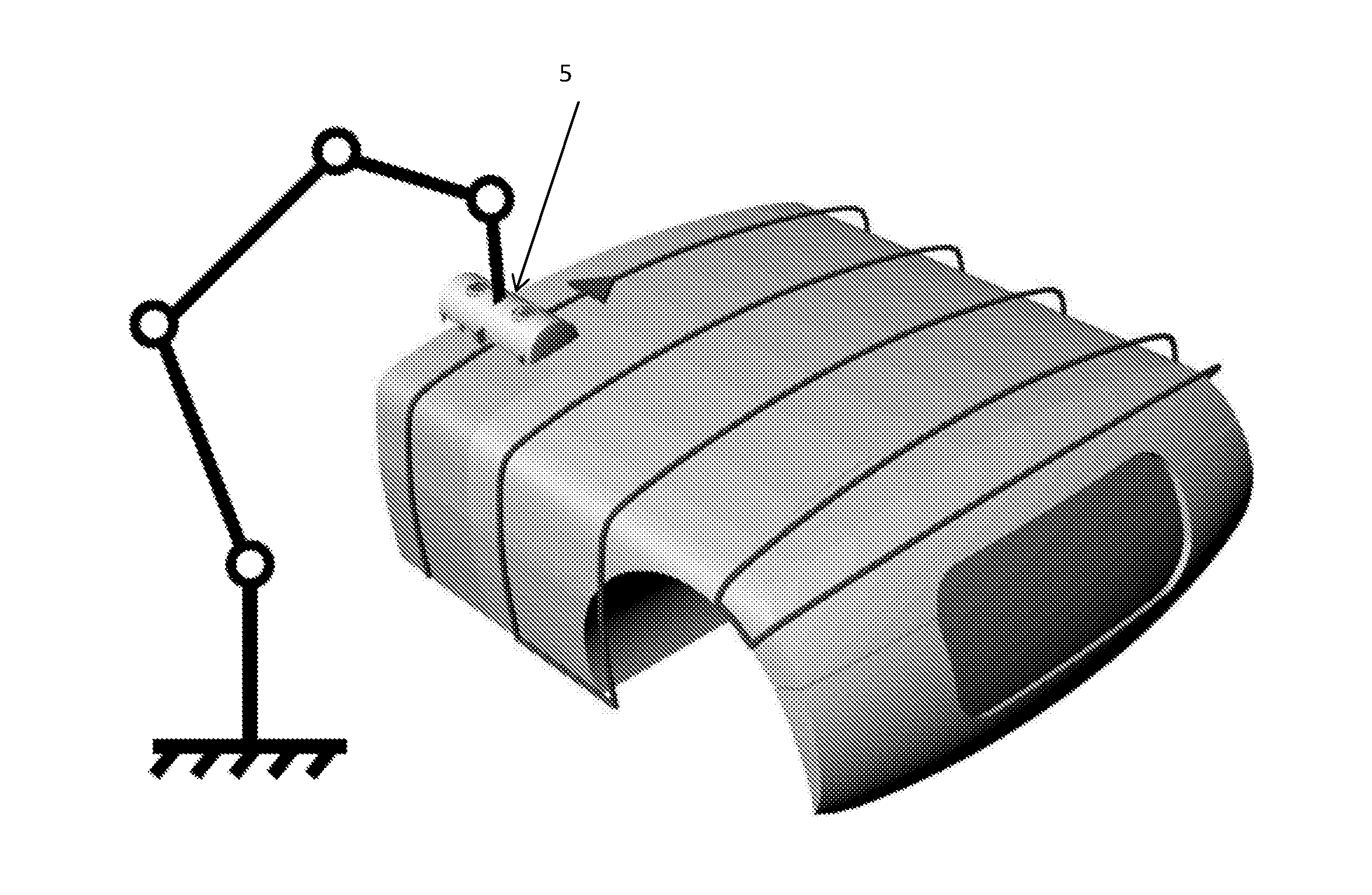
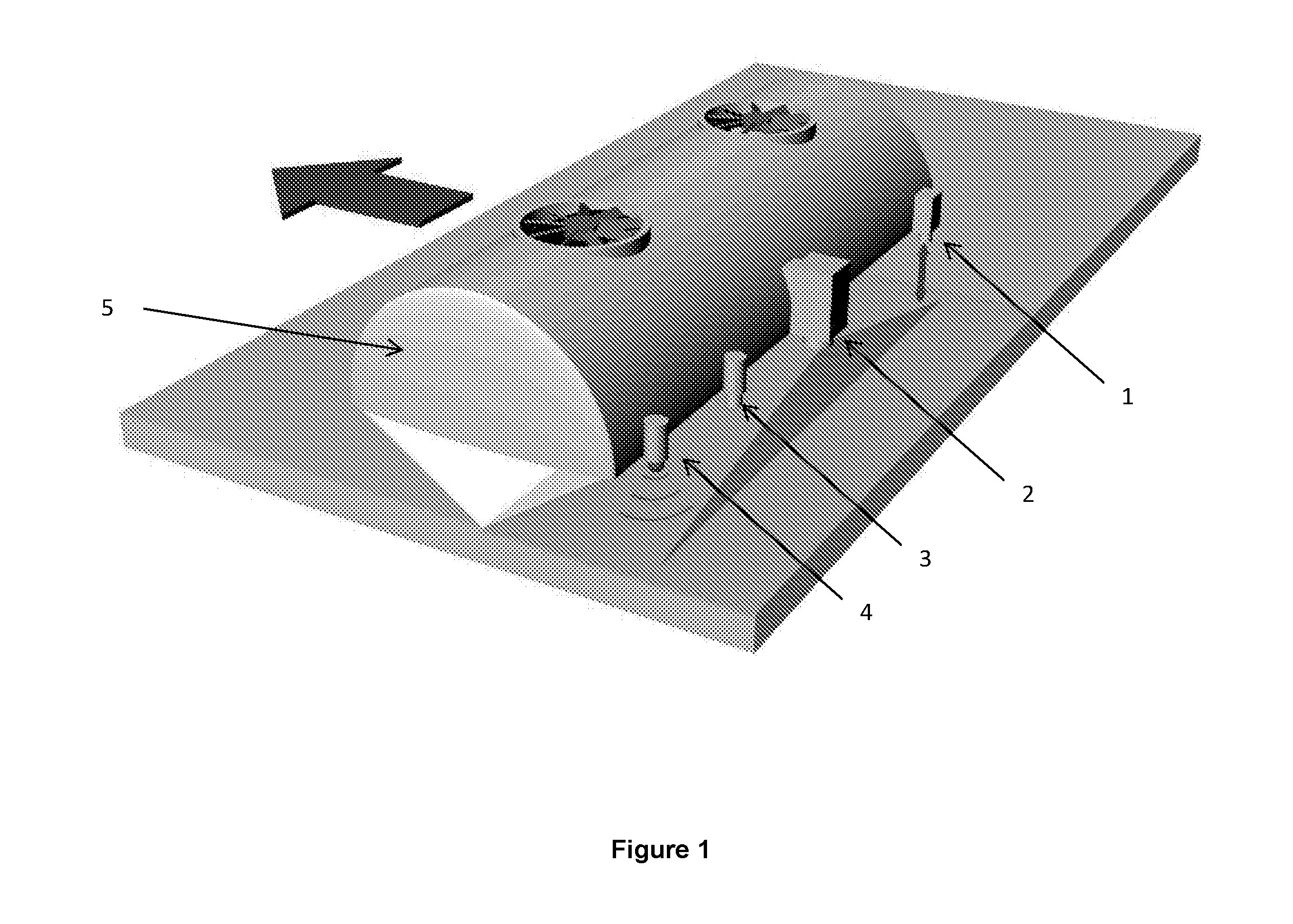
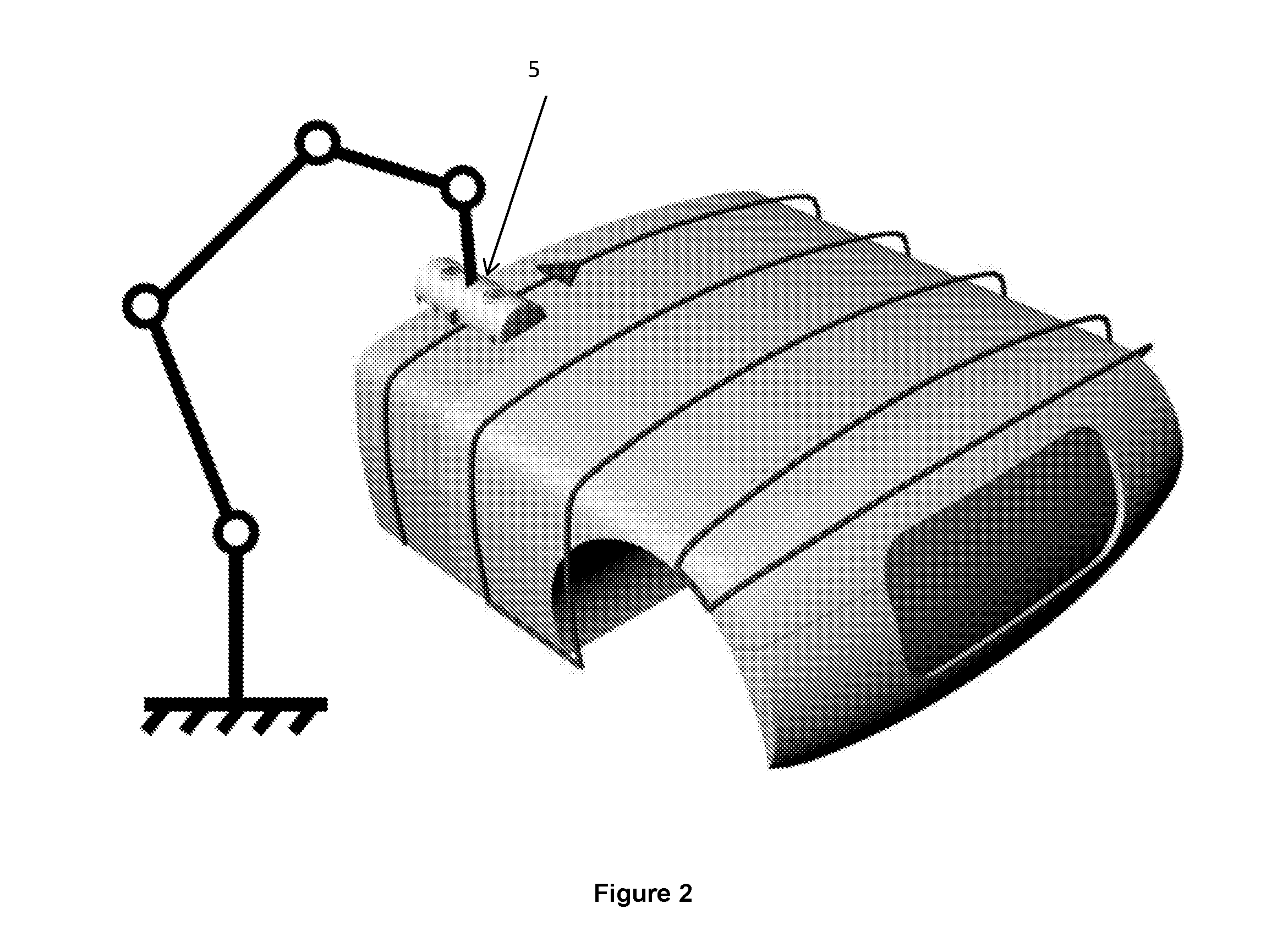
[0025]Referring to FIG. 1 there is shown an LED based curing lamp according to the present invention comprising a reflector (5) with cooling fans for removing the heat generated by the UV LED's. The multiple wavelengths from the UV LED are focused in a line on the surface of the curing material. On the backside of the reflector in relation to the moving direction of the curing material sensors are mounted for controlling the curing process. In a preferred embodiment such sensors include a laser distance measurement sensor (1), a thermographic camera (2), a photodiode for measurement of the UV LED irradiance (3), and a microphone feed-back system (4).

[0026]It is envisaged by the present invention to use the laser distance measurement sensor for measuring the distance from the bottom of the reflector to the curing material. Moreover, the thermographic camera (2) measures the temperature profile of the cured material. The camera is intelligent and gives feed back to the central compute...


PUM

PropertyMeasurementUnit
Thicknessaaaaaaaaaa

Abstract

There is provided an UV curing apparatus for the curing of a UV curable product having a UV curable coating thereon comprising at least two arrays of UV LEDs, a positioning mechanism for placing the UV curable product in the light zone of the UV LEDs, and a thermographic camera (2) for monitoring the curing of the UV curable coating, ink or adhesive. The apparatus uses a computer control unit to controls the curing process via the positioning mechanism by positioning of the product in the light zone in response to curing information received from the thermographic camera. The apparatus quickly, efficiently and effectively cures UV curable products, articles, inks, coatings, adhesives, and other object, thereby reducing the curing time and increasing the quality of the cured product.

Description

FIELD OF THE INVENTION[0001]The present invention generally relates to a method and apparatus for curing photosensitive materials.BACKGROUND OF THE INVENTION[0002]Photo-curing systems typically use mercury-arc lamps to flood the UV sensitive material with UV light. While mercury-arc lamp technology is widely used, such technology has several disadvantages. The most obvious disadvantage is the life span of the mercury bulbs used in the mercury-arc lamps. Mercury bulbs have a relatively short life, typically 100-1000 hours. Further, the mercury bulb degrades nonlinearly during its lifetime. As a result, conventional mercury-arc photocuring systems often require means to monitor and adjust the output power as the mercury bulb degrades. Further, mercury-arc lamps are typically powered on even during stand-by periods because they require cumbersome warm-up and cool-down cycles; as a result, much of the life of the mercury bulbs may be lost during these stand-by periods. Another disadvant...

Claims


Application Information

Patent Timeline
IPC IPC(8): B29C35/00
CPCB29C35/00B29C35/0805B29C2035/0827B41M7/0081B41F23/0453B05D3/067B41M7/0045B41F23/0409B41J11/00214
Inventor OESTERGAARD, JOHN ERLANDJOHANSEN, POUL V. LINDSTORFF
Owner OTHONIA CURING TECH APS
Why Eureka
Try Eureka