
Method and system for evaluating redox flow battery

a redox flow battery and battery technology, applied in the direction of electrolyte stream management, indirect fuel cells, instruments, etc., can solve the problems of reducing the capacity of the battery, reducing the pump energy required for mixing the positive and negative electrolytes with each other, and affecting the efficiency of the battery

Inactive Publication Date: 2015-08-13
OCI
View PDF2 Cites 20 Cited by
  • Summary
  • Abstract
  • Description
  • Claims
  • Application Information

AI Technical Summary

Benefits of technology

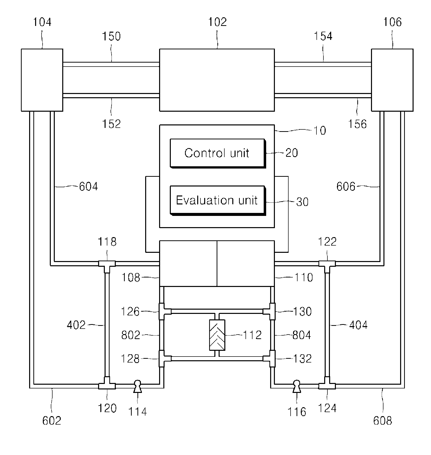
The patent text describes a method and system to evaluate a redox flow battery. The invention aims to quickly solve the issue of capacity fade in redox flow batteries by analyzing information about the positive and negative electrolytes and the valence balance. The method also aims to manage the energy of the redox flow battery efficiently and keep it running smoothly, improving its reliability and performance.

Problems solved by technology

This phenomenon causes an imbalance in the capacity of the active materials to reduce electrolyte availability, thereby reducing the battery capacity.
However, this method has disadvantages in that both the pump energy required for mixing the positive and negative electrolytes with each other and the energy of the battery in a charged state are lost and in that a large amount of time is required until the mixing of the positive and negative electrolytes (total mixing) is completed.
Meanwhile, in addition to capacity fade caused by an imbalance in the capacity of the active materials of positive and negative electrolytes, capacity fade by an imbalance in the valence of the active materials can occur.
However, a redox reaction may independently occur in only one of the electrolytes due to side reactions caused by air inflow, overvoltage and the like during the use of the battery.
However, the valence imbalance of active materials by an irreversible reaction results in permanent battery capacity fade, and for this reason, the valence balance of active materials needs to be evaluated independently of capacity fade during the evaluation of electrolytes.

Method used


Image

  • Method and system for evaluating redox flow battery
  • Method and system for evaluating redox flow battery
  • Method and system for evaluating redox flow battery

Examples


first embodiment

Mode for Evaluation of State of Charge

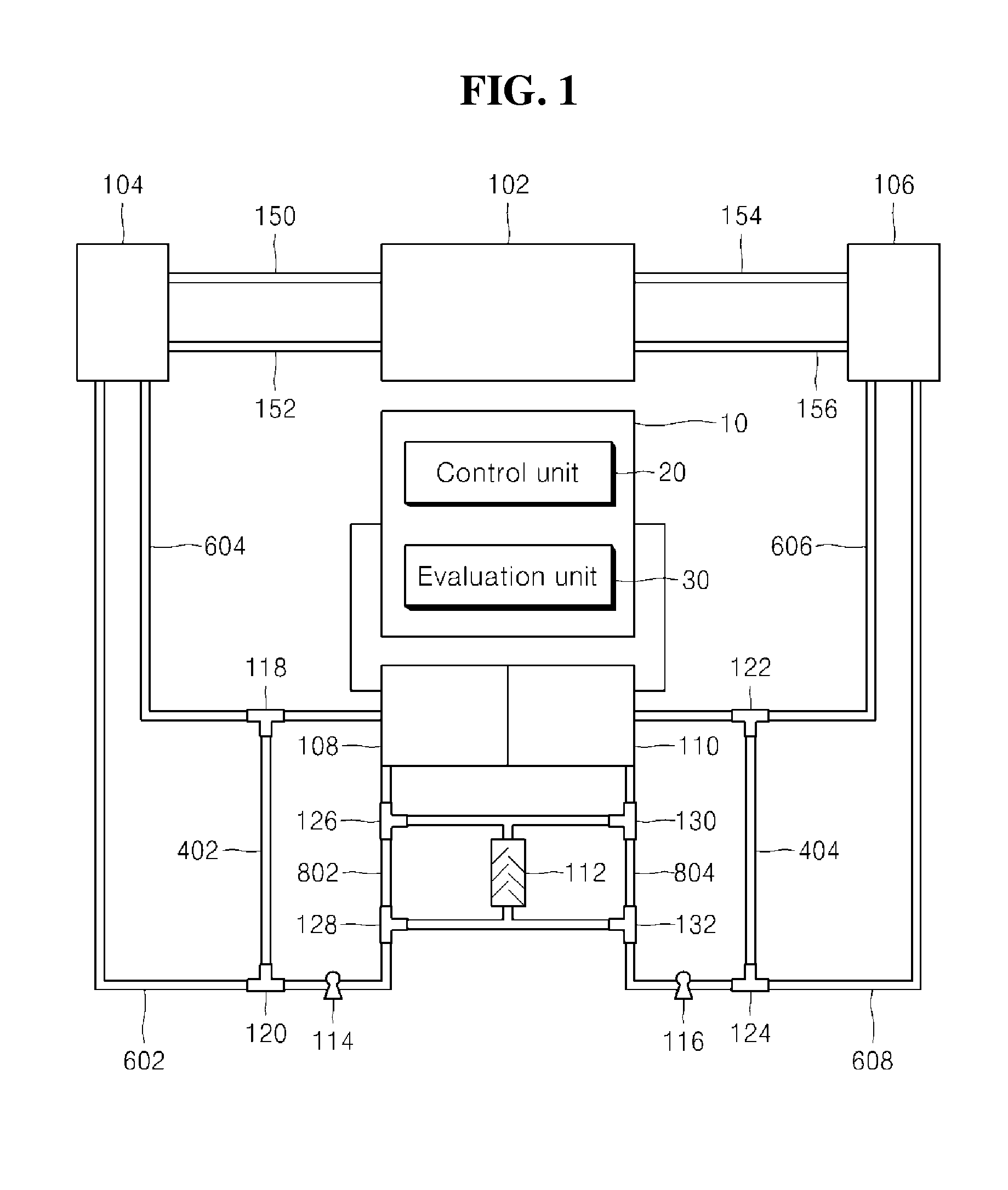
[0039]FIG. 4 is a view illustrating the operation of a redox flow battery evaluation system according to a first embodiment of the present disclosure.

[0040]Referring to FIG. 4, the control unit 20 controls the on / off state of three-way valves 118, 120, 122, 124, 126, 128, 130 and 132 to thereby control the paths of flow channels so that the electrolytes discharged from the electrolyte tanks 104 and 106 will be introduced again into the electrolyte tanks 104 and 106 after passage through the detection cells 108 and 110. The on / off states of three-way valves, which are controlled by the control unit 20 in the first embodiment, are as follows:

[0041]three-way valves 118, 120, 122, 124, 126, 128, 130 and 132: “off” state.

[0042]Specifically, the three-way valves 118, 120, 122, 124, 126, 128, 130 and 132 are all maintained in an “off” state, and the movement paths of the first and second electrolytes in this state are as follows:

[0043]movement path of ...

second embodiment

Mode for Evaluation of Capacity Fade

[0057]FIG. 6 is a view illustrating the operation of a redox flow battery evaluation system according to a second embodiment of the present disclosure.

[0058]Referring to FIG. 6, a control unit 20 is configured to control the on / off states of three-way valves 118, 120, 122, 124, 126, 128, 130 and 132 to thereby control the path of each flow channel so that electrolytes discharged from detection cells 108 and 110 will be introduced again into the detection cells 108 and 110 without passing through tanks 104 and 106 or an agitator 112. The on / off states of the three-way valves, which are controlled by the control unit 20 in the second embodiment, are as follows:

[0059]three-way valves 126, 128, 130 and 132: “off” state;

[0060]three-way valves 118, 120, 122 and 124: “on” state.

[0061]Thus, the movement paths of a first electrolyte and a second electrolyte are as follows:

[0062]movement path of first electrolyte: first detection cell 108→three-way valve 11...

third embodiment

Mode for Evaluation of Oxidation Number

[0069]FIG. 8 is a view illustrating the operation of a redox flow battery evaluation system according to a third embodiment of the present disclosure.

[0070]Referring to FIG. 8, a control unit 20 is configured to control the on / off states of three-way valves 118, 120, 122, 124, 126, 128, 130 and 132 to thereby control the path of each flow channel so that electrolytes discharged from detection cells 108 and 110 will be introduced again into the detection cells 108 and 110 after passage through an agitator 112. The on / off states of three-way valves, which are controlled by the control unit 20 in the third embodiment, are as follows:

[0071]three-way valves 118, 120, 122, 124, 126, 128, 130 and 132: “on” state.

[0072]Specifically, in the third embodiment, the three-way valves 118, 120, 122, 124, 126, 128, 130 and 132 are all maintained in an “on” state, and the movement paths of a first electrolyte and a second electrolyte in this state are as follow...


PUM


Abstract

A system for evaluating a redox flow battery according to an embodiment of the present disclosure includes: a control unit configured to control the path of a flow channel connected between a detection cell and the redox flow battery or a flow channel connected between the detection cell and an agitator; and an evaluation unit configured to evaluate any one of the state of charge, capacity fade and oxidation number balance of an electrolyte, which is used in the redox flow battery, by measuring a current or voltage of the detection cell based on the controlling of the path by the control unit. According to the present disclosure, the capacity fade problem of a redox flow battery can be quickly coped with by evaluating the information of the positive and negative electrode electrolytes on battery capacity fade and information about the valence balance of the electrolytes in situ.

Description

CROSS REFERENCE TO RELATED APPLICATION[0001]This application claims the benefit of Korean Patent Application No. 10-2014-0016075, filed on Feb. 12, 2014, entitled “METHOD AND SYSTEM FOR EVALUATING REDOX FLOW BATTERY”, which is hereby incorporated by reference in its entirety into this application.BACKGROUND[0002]1. Technical Field[0003]The present disclosure relates to a method and system for evaluating a redox flow battery, and more particularly, to a method and system of evaluating the state of the electrolyte of a redox flow battery in situ in order to overcome the capacity fade of the redox flow battery.[0004]2. Related Art[0005]A redox flow battery is an electrochemical energy storage device that stores or releases electrical energy through the redox reactions of ions contained in the electrolyte. The positive electrolyte and negative electrolyte of the redox flow battery are separated from each other by an electrolyte membrane, and diffusion occurs due to the difference in the...

Claims


Application Information

Patent Timeline
IPC IPC(8): G01R31/36H01M8/18H01M8/20H01M8/04
CPCG01R31/3606H01M8/04746H01M8/04544H01M8/20H01M8/04574H01M8/188H01M8/04276H01M8/04552H01M8/04753H01M8/04582G01R31/378Y02E60/50H01M8/04537H01M8/18
Inventor KIM, JAE-MINLEE, JI-YOUNGLEE, SEUNG-YOENKIM, SOO-WHANYE, HEE-CHANG
Owner OCI
Learn More