Coiled power device comprising a winding of a first coiling and a winding of a second coiling which cover the same portion of a magnetic core member

a technology of coiled power devices and coils, which is applied in the direction of transformers/inductances coils/windings/connections, transformer/inductances magnetic cores, inductances, etc., can solve the problem of limiting the current injection phenomenon in the power supply network, and achieve the reduction of stray capacitance of coils, the value of leakage inductance between coils at low frequencies, and the effect of improving the performance of the coiled devi

Active Publication Date: 2015-08-13
SAFRAN ELECTRICAL & POWER
View PDF3 Cites 10 Cited by
  • Summary
  • Abstract
  • Description
  • Claims
  • Application Information

AI Technical Summary

Benefits of technology

[0018]the first winding and the fourth winding cover the same portion of the first leg so as to limit the leakage inductance of the coiled power device.
[0020]Thanks to the distribution of the windings of a single coil around the two legs and thanks to the covering of turns of different coils, the value of the leakage inductance between the coils at low frequencies is significantly reduced. Furthermore, such an arrangement of the windings allows the stray capacitance of the coils to be reduced, which shifts the threshold frequency to high frequencies and limits the current injection phenomenon in the power supply network to which the device is connected.
[0021]In addition to the improved performance of the coiled device, the size and the weight thereof are unchanged, which is advantageous. Furthermore, it is not necessary to resort to capacitors or supplementary resistors to absorb the resonance between the leakage inductance and the C-Bus capacitance, thereby limiting the cost.
[0023]Preferably again, each winding comprises the same number of turns, thereby allowing the turns of different windings to overlap in pairs for optimal limitation of the leakage inductance. Preferably, the conducting wire of each winding has the same diameter and is made from the same material.
[0026]Preferably, the length of the conducting wire of the first coil is equal to the length of the conducting wire of the second coil, so that each coil has the same resistance, which promotes balanced behaviour when used as an interphase reactor.
[0027]According to a feature of the invention, each winding comprising at least two layers of turns, the layers of the first winding are alternated with the layers of the fourth winding around the first leg so as to promote interaction between the coils and limit the leakage inductance.

Problems solved by technology

Furthermore, such an arrangement of the windings allows the stray capacitance of the coils to be reduced, which shifts the threshold frequency to high frequencies and limits the current injection phenomenon in the power supply network to which the device is connected.

Method used


Image

  • Coiled power device comprising a winding of a first coiling and a winding of a second coiling which cover the same portion of a magnetic core member
  • Coiled power device comprising a winding of a first coiling and a winding of a second coiling which cover the same portion of a magnetic core member
  • Coiled power device comprising a winding of a first coiling and a winding of a second coiling which cover the same portion of a magnetic core member

Examples


Embodiment Construction

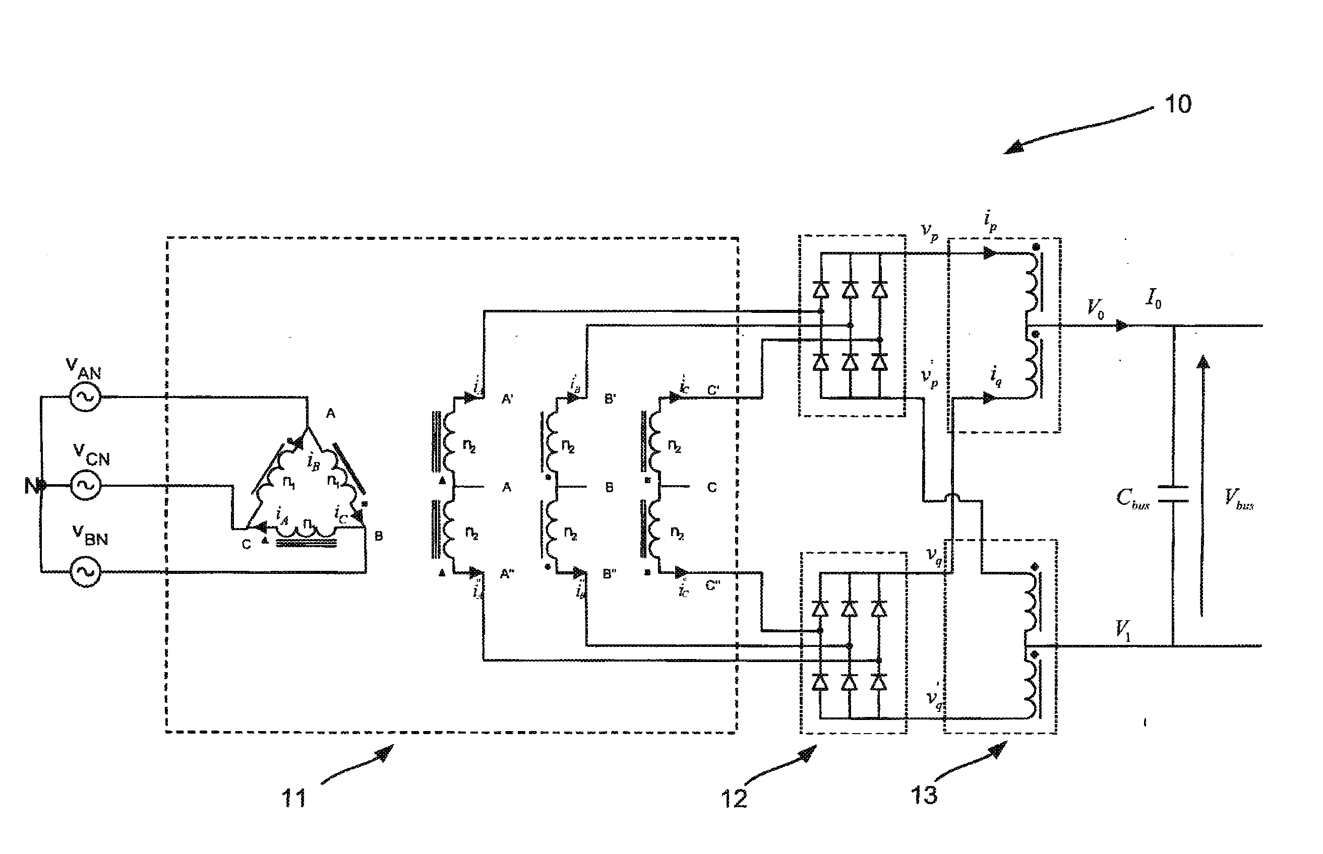
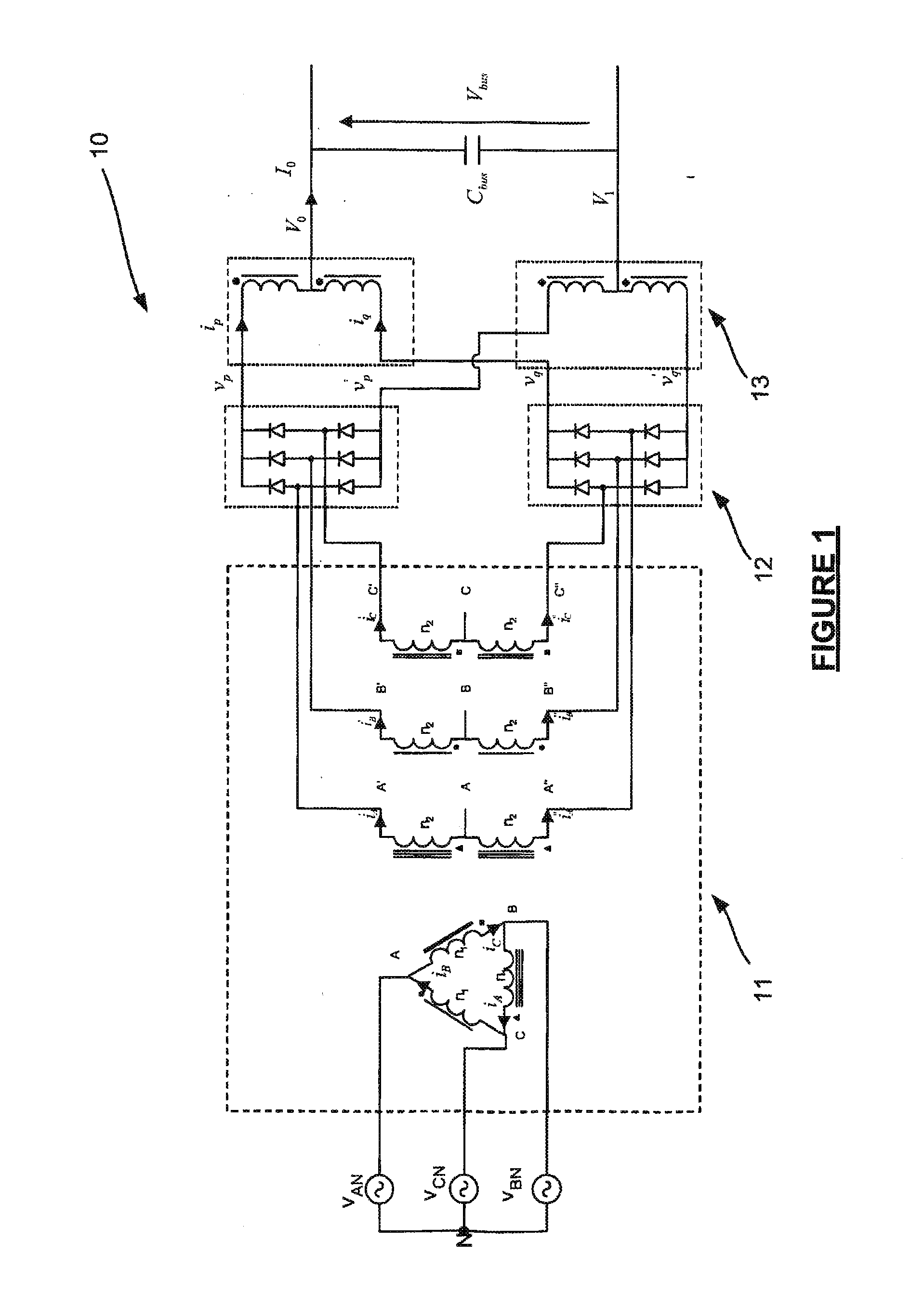
[0047]The invention will be described for an interphase reactor 3 of an AC / DC converter but it applies to any power device comprising two coupled coils on the same magnetic core, for example, for a transformer or a common mode choke.

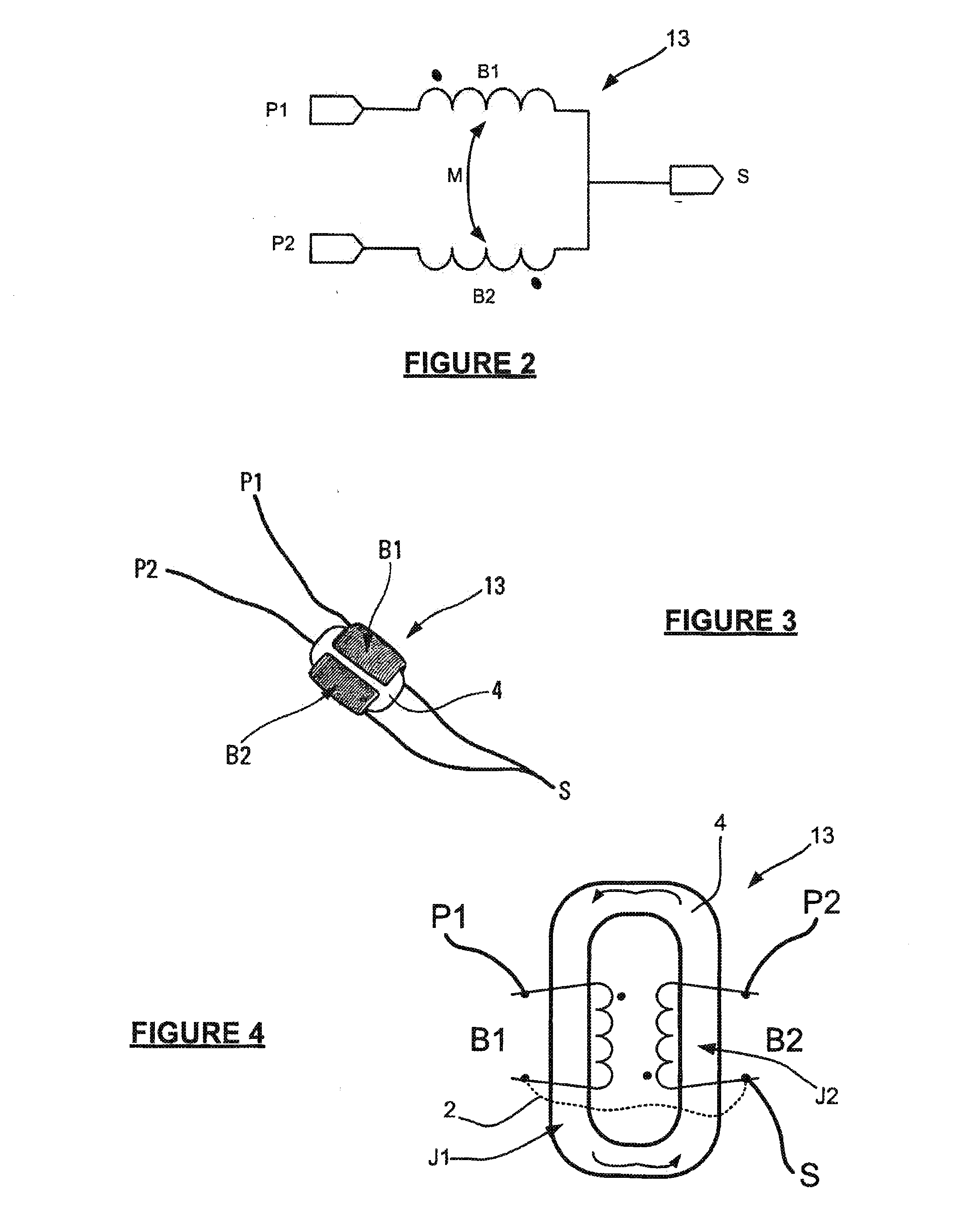
[0048]In this example, with reference to FIG. 9, the interphase reactor 3 comprises an annular magnetic core 4 defining a first leg J1 and a second leg J2 which are parallel to each other. The magnetic core 4 is closed so as to guide a magnetic flow therein as symbolised by the arrows in FIG. 9. Conventionally, the middle of the two legs J1, J2 contains a region of non-magnetic material, said area being referred to as an “air gap”.

[0049]According to the prior art, an interphase reactor comprised a first winding of conducting wires, made from copper or aluminium, around a first leg to form a first coil and a second winding of conducting wires around a second leg to form a second coil. In other words, each coil was formed around only one leg of the magneti...


PUM

PropertyMeasurementUnit
frequenciesaaaaaaaaaa
equivalent inductanceaaaaaaaaaa
leakage inductance Lfaaaaaaaaaa

Abstract

A coiled power device including a magnetic core including a first leg and a second leg which are parallel to each other, the device including a first coil and a second coil to generate mutual inductance between the coils, the first coil including a first winding of conducting wires around the first leg and a second winding of conducting wires around the second leg, the second coil including at least a third winding of conducting wires around the second leg and a fourth winding of conducting wires around the first leg, the first winding and the fourth winding covering the same portion of the first leg to limit leakage inductance of the coiled power device.

Description

GENERAL TECHNICAL FIELD AND PRIOR ART[0001]The present invention relates to the field of power electronics and, more particularly, it relates to coupled coils used for example in an interphase reactor or a transformer.[0002]Conventionally, it is known that to convert alternating voltage to direct voltage an AC / DC converter is used. Of these AC / DC converters there exists, for example, with reference to FIG. 1, a diode rectifier 10, referred to as a “twelve-pulse” diode rectifier, which conventionally comprises a transformer 11, two diode bridges 12 and two interphase reactors 13. As a reminder, an interphase reactor 13 allows the mean voltage leaving the diode bridges 12 to be induced as shown in FIG. 1. An AC / DC converter of this type is, for example, used as an uninterruptible power supply to control actuators and thus move the components of an aircraft (flaps, nacelle components).[0003]With reference more particularly to FIGS. 2 to 4, an interphase reactor 13 conventionally compri...

Claims


Application Information

Patent Timeline
Patent Type & Authority Applications(United States)
IPC IPC(8): H01F27/28H01F27/24H02M7/06
CPCH01F27/2823H01F27/24H02M7/06H01F27/38H01F2038/026H01F27/00H01F27/385
Inventor SOREL, HERVEBLEUZEN, FREDERIC
Owner SAFRAN ELECTRICAL & POWER
Why Eureka
Try Eureka