Air Gap Formation Between Bit Lines with Side Protection

Active Publication Date: 2015-08-13
SANDISK TECH LLC
View PDF4 Cites 13 Cited by
  • Summary
  • Abstract
  • Description
  • Claims
  • Application Information

AI Technical Summary

Benefits of technology

[0009]According to an example of formation of a memory integrated circuit, air gaps are formed between bit lines to reduce bit line-to-bit line capacitance. Air gaps are formed by etching to remove sacrificial material from between bit lines, which has been found to cause damage to bit lines in some cases. Bit lines may be protected from etch damage during etching of sacrificial material to form air gaps. Sacrificial material may be selectively oxidized prior to depos

Problems solved by technology
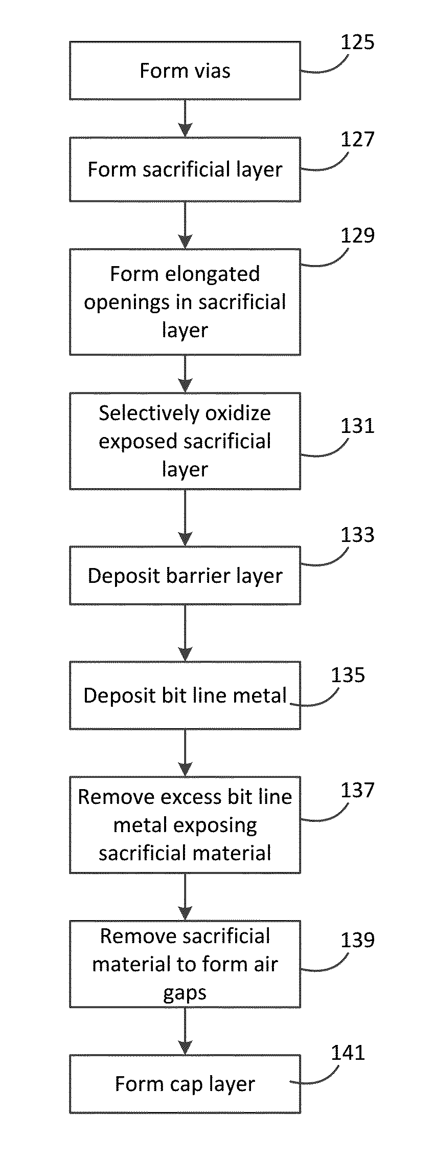
Air gaps are formed by etching to remove sacrificial material from between

Method used


Image

  • Air Gap Formation Between Bit Lines with Side Protection
  • Air Gap Formation Between Bit Lines with Side Protection
  • Air Gap Formation Between Bit Lines with Side Protection

Examples


Embodiment Construction
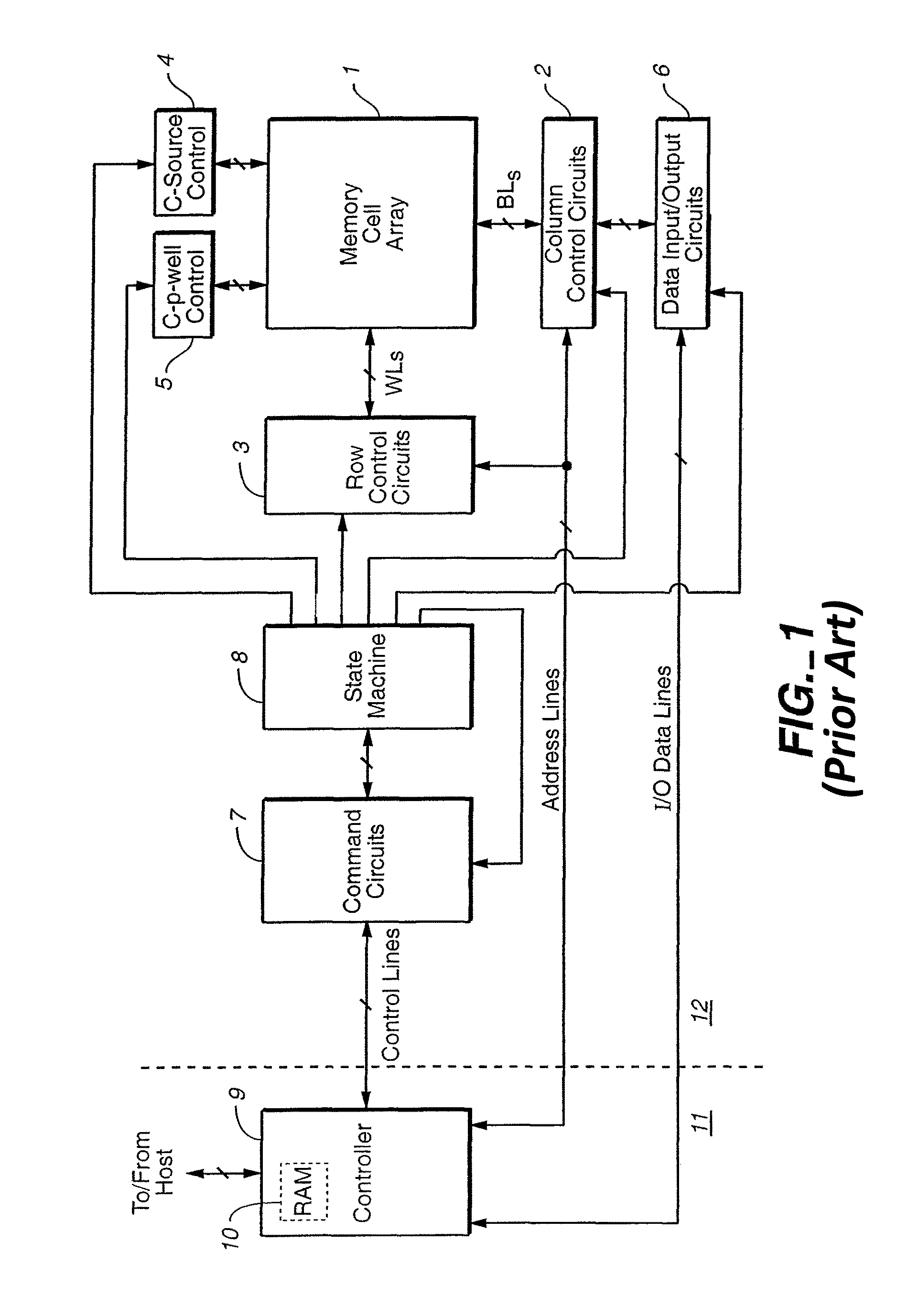
Memory System

[0037]Semiconductor memory devices include volatile memory devices, such as dynamic random access memory (“DRAM”) or static random access memory (“SRAM”) devices, non-volatile memory devices, such as resistive random access memory (“ReRAM”), electrically erasable programmable read only memory (“EEPROM”), flash memory (which can also be considered a subset of EEPROM), ferroelectric random access memory (“FRAM”), and magnetoresistive random access memory (“MRAM”), and other semiconductor elements capable of storing information. Each type of memory device may have different configurations. For example, flash memory devices may be configured in a NAND or a NOR configuration.

[0038]The memory devices can be formed from passive and / or active elements, in any combinations. By way of non-limiting example, passive semiconductor memory elements include ReRAM device elements, which in some embodiments include a resistivity switching storage element, such as an anti-fuse, phase chan...


PUM


Abstract

Air gaps are formed between bit lines by etching to remove sacrificial material from between bit lines. Bit lines are protected from etch damage. Sacrificial material may be selectively oxidized prior to deposition of bit line metal so that protective oxide lies along sides of bit lines during etch. Portions of protective material may be selectively formed on tops of bit lines prior to etching sacrificial material.

Description

CROSS REFERENCE TO RELATED APPLICATIONS[0001]The present application claims the benefit of U.S. Provisional Patent Application No. 61 / 939,095, entitled, “Metal layer air gap for device performance improvement,” filed on Feb. 12, 2014, which is hereby incorporated by reference in its entirety.[0002]The present application is related to U.S. patent application entitled, “Air gap formation between bit lines with top protection,” filed on the same date as the present application.BACKGROUND OF THE INVENTION[0003]This invention relates generally to non-volatile semiconductor memories of the flash memory type, their formation, structure and use.[0004]There are many commercially successful non-volatile memory products being used today, particularly in the form of small form factor cards, USB drives, embedded memory, and Solid State Drives (SSDs) which use an array of flash EEPROM cells. An example of a flash memory system is shown in FIG. 1, in which a memory cell array 1 is formed on a mem...

Claims


Application Information

Patent Timeline
IPC IPC(8): H01L23/532H01L27/115
CPCH01L23/5329H01L27/11529H01L23/53257H01L23/53266H01L23/53228H01L23/5222H01L23/53295H01L2924/0002H01L21/76834H01L21/7682H01L23/53238H10B41/41H01L2924/00H01L21/76802H01L21/76879
Inventor SEL, JONG SUNGUNJI-YONEOKA, MARIKATAKEGUCHI, NAOKIPARK, CHANPHAM, TUAN D.TOKUNAGA, KAZUYA
Owner SANDISK TECH LLC
Why Eureka
Try Eureka