
Application layer session routing

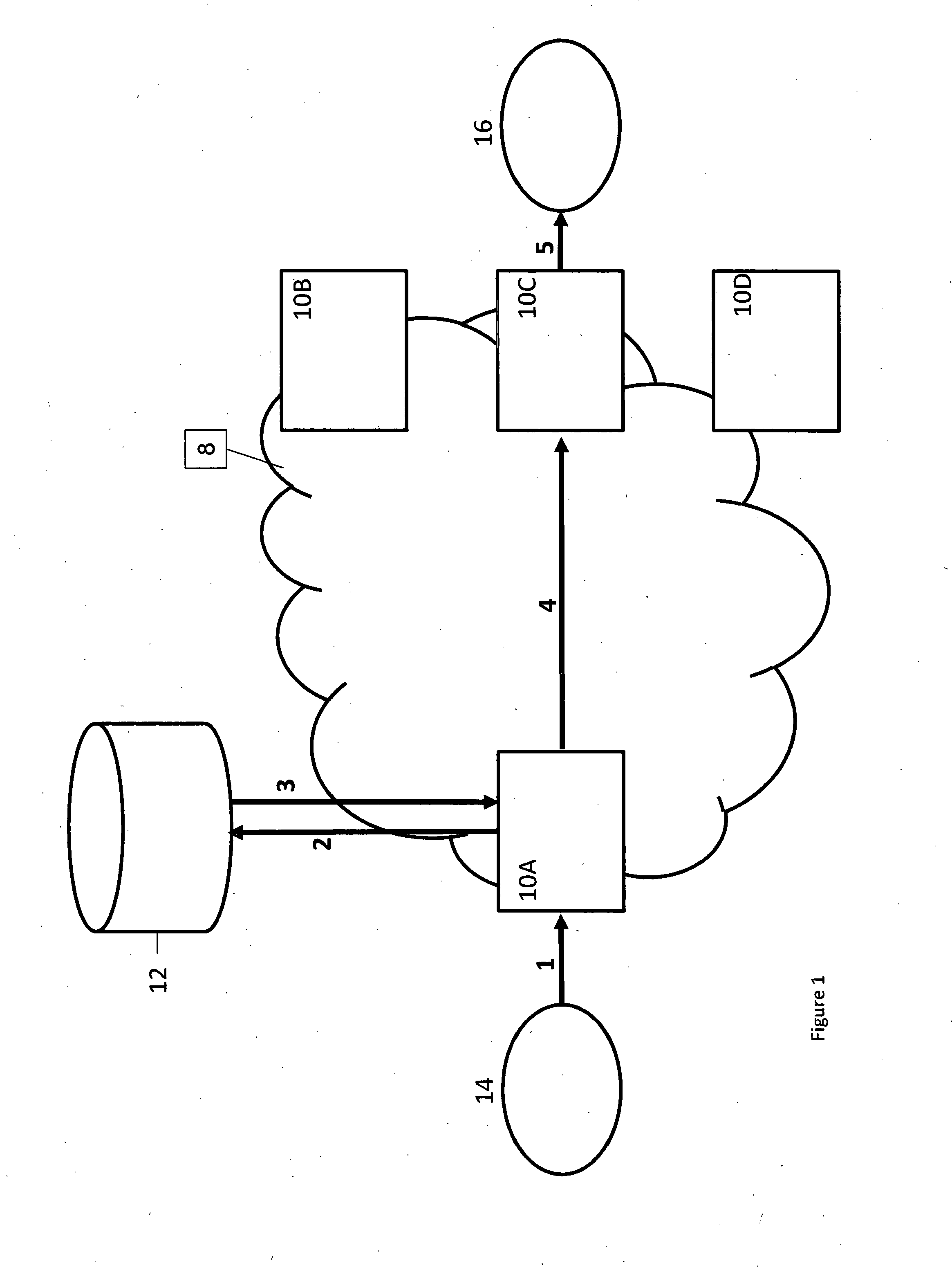
a session routing and application layer technology, applied in the field of application layer session routing, can solve the problems of significant management problems, inability to respond to any session setup signalling, high cost and premium on remote international nodes, etc., and achieve the effect of reducing the resources needed for managemen

Active Publication Date: 2015-08-13
BRITISH TELECOMM PLC
View PDF6 Cites 15 Cited by
  • Summary
  • Abstract
  • Description
  • Claims
  • Application Information

AI Technical Summary

Benefits of technology

The invention improves session routing in networks by using a centralised server that can quickly determine which elements are available for use, reducing the time and resources needed for routing calls. It also reduces the number of messages exchanged between nodes, resulting in reduced processing and bandwidth overhead. Additionally, the session control edge node can dynamically discover and signal the availability of other networks it serves.

Problems solved by technology

It may have become isolated from the network through transmission faults or be out of service through equipment fault or planned maintenance and therefore unable to respond to any session setup signalling.
However, bilateral heartbeat messages cause a problem as flat network architectures scale the number of session control nodes.
Therefore this message rate grows as a square of the nodes within a network, which on a large scale, such as a national or global network, can use significant node processing and network bandwidth, which may be costly and at a premium on remote international nodes.
It also causes a significant management problem every time a node is added or permanently removed within the overall network as this network topology change has to be distributed to all other nodes.
Without knowledge of the packet performance of the bearer path, the CCM may establish calls that result in poor voice quality or call setup failure.

Method used


Image

  • Application layer session routing
  • Application layer session routing
  • Application layer session routing

Examples


Embodiment Construction

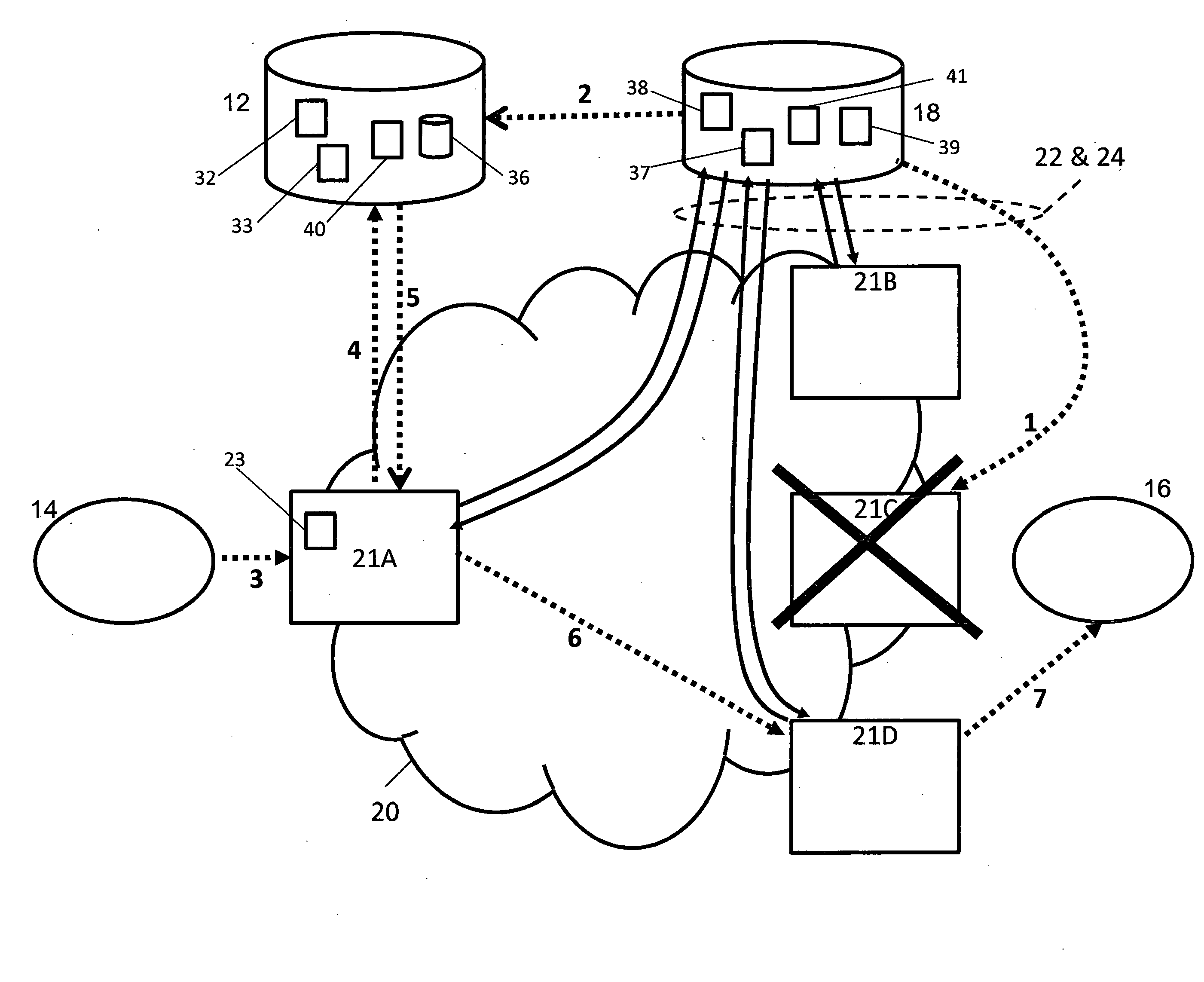
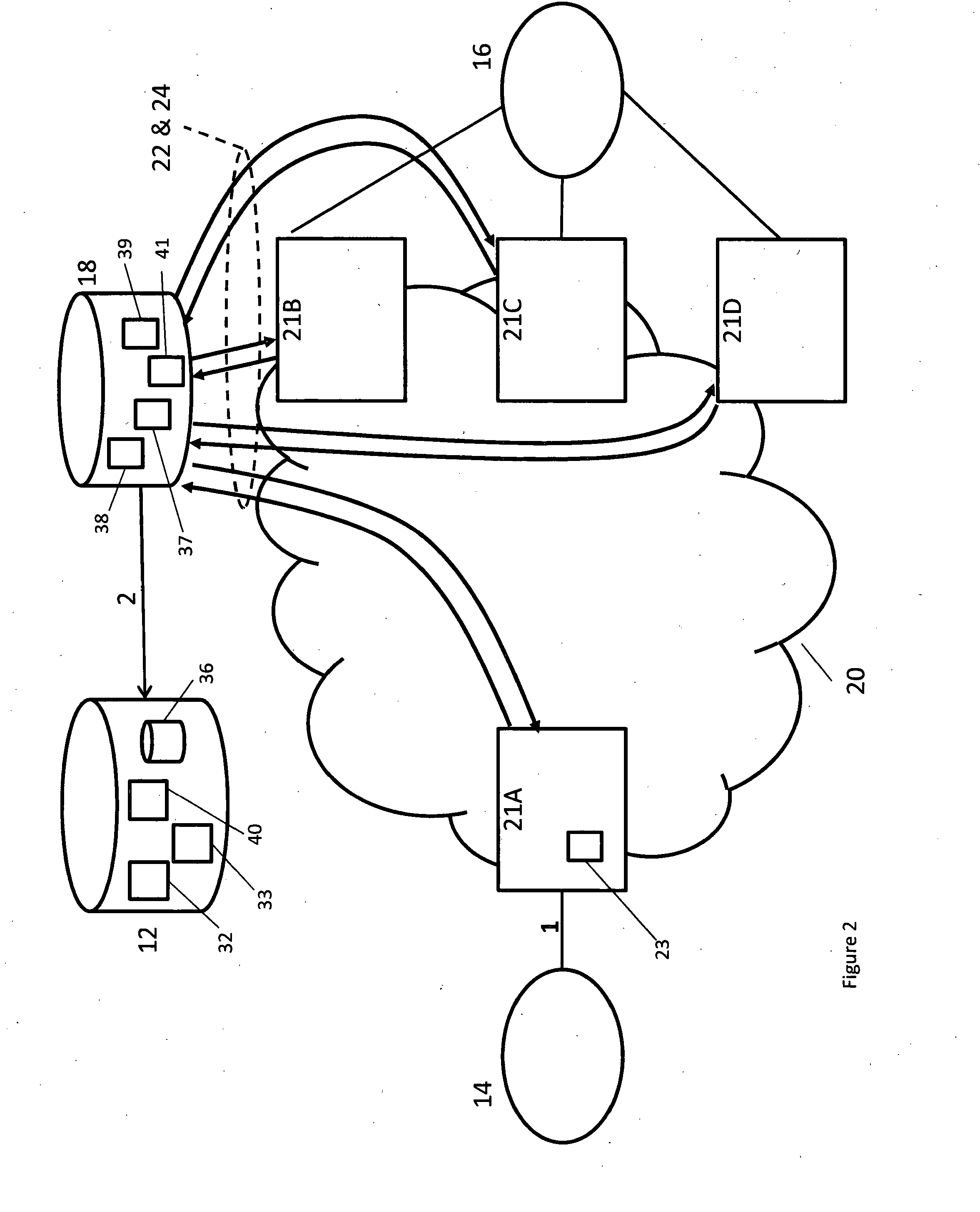
[0030]A first exemplary embodiment of the present invention will now be described in relation to FIG. 2. The Voice and multimedia network 20 of FIG. 2 is a large transit network where many different operators interconnect. The network 20 comprises a number of session control edge nodes 21A-D, which terminates the interconnection transmission to different operators, and a centralised routing policy server 12. The routing policy server 12 comprises a processor 32, a routing policy store 36, a selection and modification module 40, and one or more memories 33. The edge nodes 21 can be for example Session Border Controllers, Call Servers, Soft switches, Application servers, Application Gateways and Media Gateways controllers. In addition, there is a logical centralised reachability server 18 incorporated into the network. The centralised reachability server 18 comprises a processor 37, one or more memories 39 and a session control edge node status module 38 and for certain embodiments al...


PUM


Abstract

A method and server system for providing application layer session routing based on network element availability. A server system (12, 18) is arranged to monitor the abilities of session control edge nodes (21A-D) within a large VoIP and Multimedia transit network (20) to handle session set-up requests. A status module (38) in the server system receives status messages (22, 24) from the edge nodes and based on these messages a selection and modification module (40, 41) selects which edge nodes (21A-D) as well as which of their associated interconnects to other networks to include in a response (5) to a routing request (4) from a source node (21A-D).

Description

FIELD OF INVENTION[0001]The present invention relates to Voice over Internet Protocol (VoIP) and multimedia session routing and especially to a method and system for application layer session routing in transit networks between different service providers.BACKGROUND OF INVENTION[0002]Traditional voice networks usually have a hierarchy of switches that are used to route calls from one local exchange to another via transit and potentially international transit switches. Calls are passed from switch to switch, which each makes its own local routing decision based on the telephone number (end address) and also in part on the service state of the TDM link used to reach the next switch. If a link is busy, out of service or indeed if the switch is out of service, the proceeding switch uses alternate routes to bypass the nodes affected by a service congestion or equipment outage.[0003]In networks implementing VoIP technology the call control and the media transport are separated into indepe...

Claims


Application Information

Patent Timeline
Patent Type & Authority Applications(United States)
IPC IPC(8): H04L12/725H04L12/707H04L12/24H04L29/06H04L45/24
CPCH04L45/3065H04L65/1046H04L41/0686H04L45/22H04L41/0659H04L65/1069H04L45/306H04L45/64H04L65/80
Inventor JENKINS, IAN WILLIAM GEORGE
Owner BRITISH TELECOMM PLC
Learn More