Stationary source computed tomography and ct-mri systems

a computed tomography and station source technology, applied in the field of computed tomography, can solve the problems of difficult to uniquely reconstruct an roi from truncated local data, many important problems are localized, and the radiation dose is reduced, so as to speed up the temporal resolution and speed up the resolution

Active Publication Date: 2015-08-20
VIRGINIA TECH INTPROP INC
View PDF3 Cites 53 Cited by
  • Summary
  • Abstract
  • Description
  • Claims
  • Application Information

AI Technical Summary

Benefits of technology

[0019]To this end, the inventors provide a stationary cardiac CT architecture that combines the latest developments in interior tomography and distributed x-ray source. The inventive stationary CT architecture provides imaging at a faster temporal resolution and lower radiation dose. In exemplary embodiments, the architecture features three stationary distributed x-ray sources and three rotating x-ray detectors. In some aspects, each of the three sources contains about 100 x-ray beams. The three detectors may have a narrow transaxial width, and acquire truncated projection data for a 200 mm region-of-interest in diameter. In synchrony with the rotating detectors, the three source arrays may be electronically activated to simulate the spinning of three conventional single-beam x-ray sources. Three source-detector chains can work in parallel to acquire three projections simultaneously and speed up temporal resolution. X-ray beams may be restricted to cover only the local region to reduce full-body radiation dose. The inventive architecture can enable 50 ms temporal resolution and greatly reduced radiation dose.
[0020]Further, the inventors provide a novel design of a CT-MRI system for Omni-tomography and a process to make this CT-MRI scanner based on the stationary CT architecture. In embodiments, the CT-MRI system for Omni-tomography provides for ease of integration and shielding without significant electromagnetic interference, based on a design of stationary x-ray sources and detectors in the CT subsystem. In some aspects, the omni-tomographic reconstruction may be made based on a dictionary / atlas framework. The novel CT-MRI scanners are useful for quantitative and interventional opportunities in cost-effective biomedical applications, such as early screening, disease staging, therapeutic assessment, interventional guidance, and other aspects of “personalized medicine”.

Problems solved by technology

On the other hand, many important problems are localized, or at least often observed within a relatively small region of interest (ROI).
However, precise prior knowledge of a sub-region can be often unavailable.
It was considered impossible to uniquely reconstruct an ROI from truncated local data, which is known as the interior problem.
While there are intrinsic limitations with both approaches, the seamless fusion of multiple imaging modalities has been challenging due to the physical (especially spatial) conflicts of these scanners.
However, increasing the temporal resolution via an even faster gantry rotation speed appears to be beyond today's mechanical limits.
However, as demonstrated by the dynamic spatial reconstructor (DSR) in the 1980s and depending on the actual geometry used, the number of sources was limited by the proximity of adjacent x-ray sources to prevent adjacent beams from overlapping.
Previously, a number of dose reduction techniques have been developed, but the success is far from sufficient.
However, the limitations of temporal and spatial resolution and radiation dose inhibit the utilization of CVCT for more clinical applications.
The specific primary bottlenecks of the current CVCT include the difficulties of the synchronization with high or arrhythmic heart rates, the inability to measure blood flow, the detection of vulnerable plaques, the separation of calcium from iodine signals, the study of myocardial micro-vascular structure and perfusion, as well as the risk of ionizing radiation exposure.
Further, current cardiac computed tomography (CT) is too slow for high or irregular heart rates, and its high radiation dose is a public concern.

Method used


Image

  • Stationary source computed tomography and ct-mri systems
  • Stationary source computed tomography and ct-mri systems
  • Stationary source computed tomography and ct-mri systems

Examples


examples

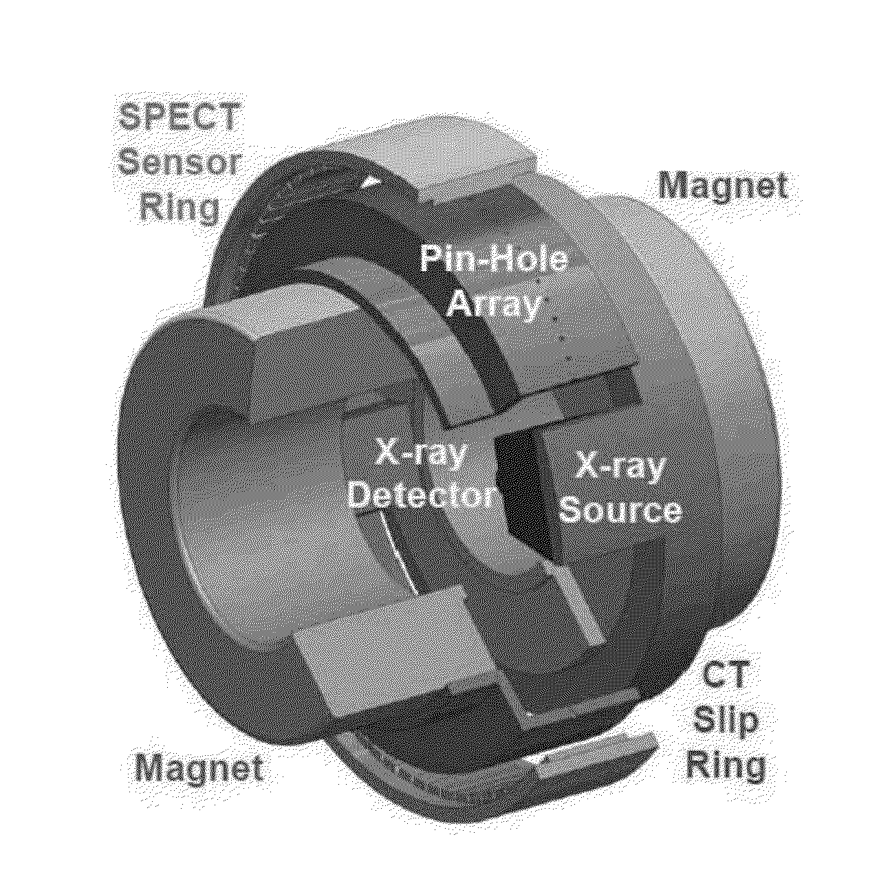
[0102]Cardiovascular computed tomography (CVCT) has been successfully applied for the diagnosis of a series of heart diseases. However, the limitations of temporal and spatial resolution and radiation dose inhibit the utilization of CVCT for more clinical applications. The specific primary bottlenecks of the current CVCT include the difficulties of the synchronization with high or arrhythmic heart rates, the inability to measure blood flow, the detection of vulnerable plaques, the separation of calcium from iodine signals, the study of myocardial micro-vascular structure and perfusion, as well as the risk of ionizing radiation exposure. The recent technical innovations in the fields of x-ray sources and reconstruction methods indicate the immense potential for CVCT advancement. An innovative cardiac CT architecture is provided to overcome these obstacles, which systematically integrates carbon nanotube (CNT) x-ray sources and interior tomography methods. This novel architecture can ...


PUM


Abstract

The present invention provides stationary CT architecture for imaging at a faster temporal resolution and lower radiation dose. In embodiments, the architecture features stationary distributed x-ray sources and rotating x-ray detectors. Provided is a stationary source computed tomography (CT) architecture comprising: a detector disposed on a rotatable gantry; an x-ray source disposed on a fixed ring; wherein the detector is disposed on the gantry in a manner such that the detector is capable of rotating around a subject and of receiving a signal from the x-ray source. Embodiments of the invention include a CT-MRI scanner comprising the stationary CT architecture.

Description

CROSS-REFERENCE TO RELATED APPLICATIONS[0001]This application relies on the disclosure of and claims priority to and the benefit of the filing date of U.S. Provisional Application No. 61 / 768,192, filed Feb. 25, 2013, and U.S. Provisional Application No. 61 / 703,562, filed Sep. 20, 2012, the disclosure of each of which is hereby incorporated by reference herein in their entireties.STATEMENT OF GOVERNMENT INTEREST[0002]This invention was made with government support under grant R01 EB011785 awarded by the National Institutes of Health, National Institute of Biomedical Imaging and Bioengineering. The government has certain rights in the invention.BACKGROUND OF THE INVENTION[0003]1. Field of the Invention[0004]The present invention relates to computed tomography. More particularly, the present invention relates to a computed tomography architecture comprising stationary X-ray sources, and omni-tomography, including for examples, CT-MRI, based on such stationary CT architecture.[0005]2. D...

Claims


Application Information

Patent Timeline
Patent Type & Authority Applications(United States)
IPC IPC(8): A61B6/00A61B5/00A61B5/055A61B8/13G01R33/48A61B6/03
CPCA61B6/032A61B6/035A61B6/4007A61B6/4078A61B6/4233A61B6/4429A61B6/503A61B5/055A61B6/508A61B6/583A61B5/0035A61B6/4417A61B5/0059A61B6/037A61B6/4014A61B8/13G01R33/4812
Inventor WANG, GECAO, GUOHUA
Owner VIRGINIA TECH INTPROP INC
Why Eureka
Try Eureka