
Reflective varifocal lens and imaging system including the same

a varifocal lens and reflector technology, applied in the field of optical systems, can solve the problems of short life of the method, low precision, friction, etc., and achieve the effects of wide range of lens focus changes, simple structure, and easy miniaturization or making

Inactive Publication Date: 2015-08-20
ELECTRONICS & TELECOMM RES INST
View PDF6 Cites 7 Cited by
  • Summary
  • Abstract
  • Description
  • Claims
  • Application Information

AI Technical Summary

Benefits of technology

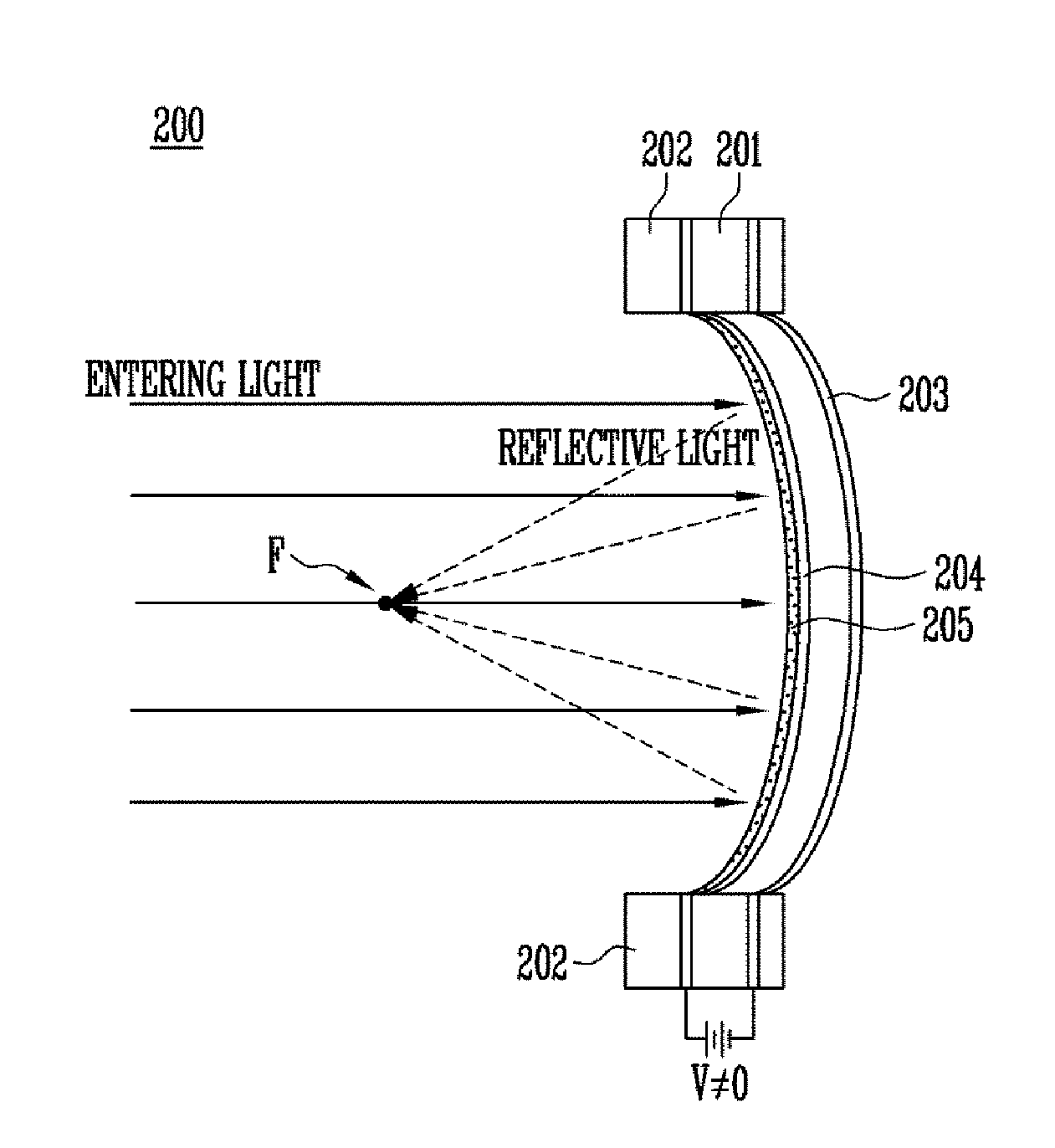
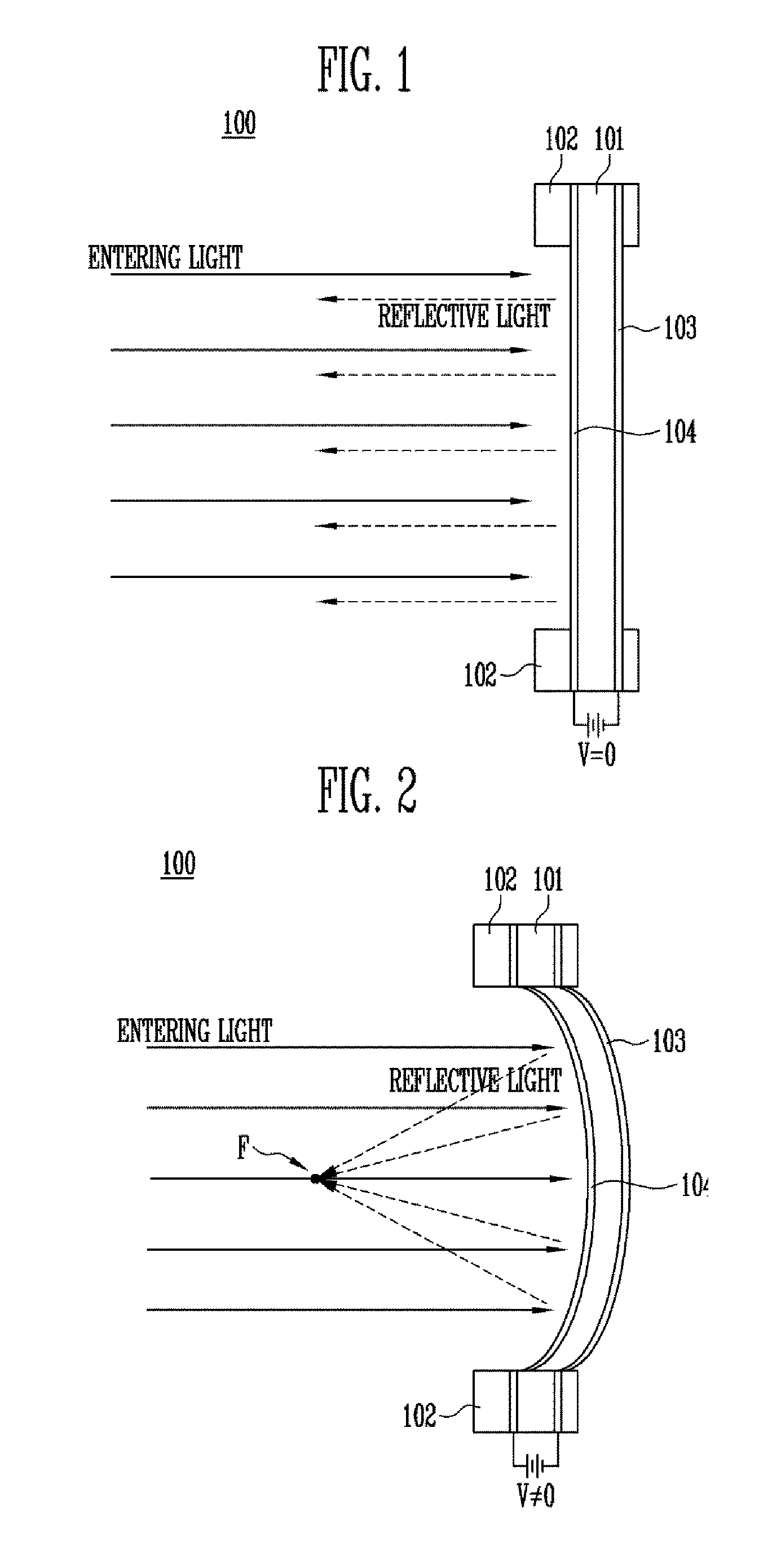
The present patent provides a reflective varifocal lens that uses a variable material to change its focal length. This lens has a simple structure that can be made smaller and can be used in imaging systems. The lens is driven electrically, which makes it very easy to miniaturize and change the focus at high speed. This reflective varifocal lens does not use physical force or pressure, but is a new and innovative technology for optical applications.

Problems solved by technology

The VCM method is a method of using the current flowing through a coil and electromagnetic force by a magnetic, which method has limitations such as electromagnetic waves and limitations in the degree of precision, while the piezo method is a method of using the friction of a stator and rotator, which method has a short lifespan due to friction and is expensive.
Furthermore, the optical zoom function is a method using a step motor, wherein a lead screw is rotated by a driver that makes rotational movement thereby linearly moving a mobile unit and thus has disadvantages of friction of the gear part and noise and so forth.
As in the aforementioned examples, most of conventional technologies are difficult to produce due to their complex structures, and have limitations in miniaturizing their sizes.
Furthermore, most of conventional reflective varifocal lens technologies use pressures of gas or fluid, or electromagnetic force.
Those technologies using pressures of gas or fluid need a pressure adjustment apparatus, and thus it is difficult to reduce the size or make them into arrays.
Furthermore, due to their complex producing process and structure, the manufacturing costs are very high.

Method used


Image

  • Reflective varifocal lens and imaging system including the same
  • Reflective varifocal lens and imaging system including the same
  • Reflective varifocal lens and imaging system including the same

Examples


Embodiment Construction

[0040]Hereinafter, embodiments will be described in greater detail with reference to the accompanying drawings. Embodiments are described herein with reference to cross-sectional illustrations that are schematic illustrations of embodiments (and intermediate structures). As such, variations from the shapes of the illustrations as a result, for example, of manufacturing techniques and / or tolerances, are to be expected. Thus, embodiments should not be construed as limited to the particular shapes of regions illustrated herein but may include deviations in shapes that result, for example, from manufacturing. In the drawings, lengths and sizes of layers and regions may be exaggerated for clarity. Like reference numerals in the drawings denote like elements.

[0041]Terms such as ‘first’ and ‘second’ may be used to describe various components, but they should not limit the various components. Those terms are only used for the purpose of differentiating a component from other components. For...


PUM


Abstract

Provided herein is a reflective varifocal lens configured to change a focal length using an electric signal, the lens including a first electrode layer having conductivity; an electric active polymer layer formed on the first electrode layer; a second electrode layer having conductivity formed on the electric active polymer layer; and a reflective layer configured to reflect a light entering towards the first electrode layer or second electrode layer, wherein a shape of the electric active polymer layer is changed by the electric signal being applied to the first electrode layer and second electrode layer, and as the shape of the electric active polymer layer changes, a shape of the reflective layer changes, thereby changing a focal length of a reflective light.

Description

CROSS-REFERENCE TO RELATED APPLICATION[0001]The present application claims priority to Korean patent application numbers 10-2014-0018684 filed on Feb. 18, 2014 and 10-2015-0006136 filed on Jan. 13, 2015, the entire disclosure of which is incorporated herein in its entirety by referenceBACKGROUND[0002]1. Field of Invention[0003]Various embodiments of the present disclosure relate to an optical system, and more particularly, to a reflective varifocal lens and an imaging system including the same.[0004]2. Description of Related Art[0005]Due to the recent development of display technologies such as cameras, mobile terminals, projectors, and TVs that have their bases on digital technologies, there is a demand for high-resolution screens and miniaturized optical systems related thereto. Furthermore, as there is a growing emphasis on miniaturization and convenience of an optical system to obtain high resolution images, researches thereon are being conducted proactively.[0006]Especially, as...

Claims


Application Information

Patent Timeline
Patent Type & Authority Applications(United States)
IPC IPC(8): G02B13/00H04N5/225G02B26/08G02B17/06G02B27/14
CPCG02B13/0075G02B26/0825G02B13/0015G02B13/0065G02B17/0694G02B27/14
Inventor PARK, SUN TAKYUN, SUNG RYULPARK, BONG JENAM, SAE KWANGKYUNG, KI UK
Owner ELECTRONICS & TELECOMM RES INST
Learn More