Method and apparatus for doppler radar signal recovery of target displacement

a technology of target displacement and radar signal, which is applied in the field of method and apparatus for target displacement recovery of doppler radar signal, can solve problems such as system noise and non-ideality

Active Publication Date: 2015-08-27
UNIV OF FLORIDA RES FOUNDATION INC
View PDF2 Cites 26 Cited by
  • Summary
  • Abstract
  • Description
  • Claims
  • Application Information

AI Technical Summary

Benefits of technology

[0003]Embodiments relate to a method and apparatus for detecting a movement of a target. Embodiments can send a radar signal at the target and process the signal reflected by the target to identify the movement. The movement can have one or more components that have a predominant frequency, such as a frequency of vibration. A specific embodiment can use a quadrature receiver to process the received signal to produce a base band output signal having an in-phase (I) and a quadrature-phase (Q) outputs. Embodiments of the subject method can cross-reference the in-phase (I) and quadrature-phase (Q) outputs and recover real target movement frequency directly in the time domain. In embodiments, the system nonlinearity can be identified and removed, as such nonlinearity does not happen simultaneously on the I and Q channels, due to the 90 degree phase shift between the I and Q channels. Embodiments can detect two, or more, periodic movements having different frequencies and, optionally, having different magnitudes. Embodiments of the subject method can provide robust detection of periodic vibrations of a target using Doppler radar. Embodiments can use radar signals having frequencies near 60-GHz, and other frequencies where one or more of the target displacement magnitudes is comparable to the wavelength of the radar signal, λ. Embodiments can be applied to other wavelength and frequency ranges, including, but not limited to, the wavelength range 0.1-0.

Problems solved by technology

Most of the existing analysis on, and techniques for accommodating for, Doppler radar nonlinearity is based on Bessel functions and based on t

Method used


Image

  • Method and apparatus for doppler radar signal recovery of target displacement
  • Method and apparatus for doppler radar signal recovery of target displacement
  • Method and apparatus for doppler radar signal recovery of target displacement

Examples


Embodiment Construction

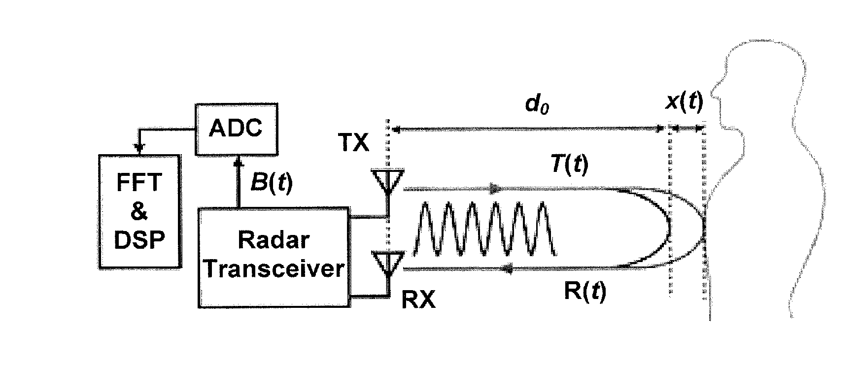
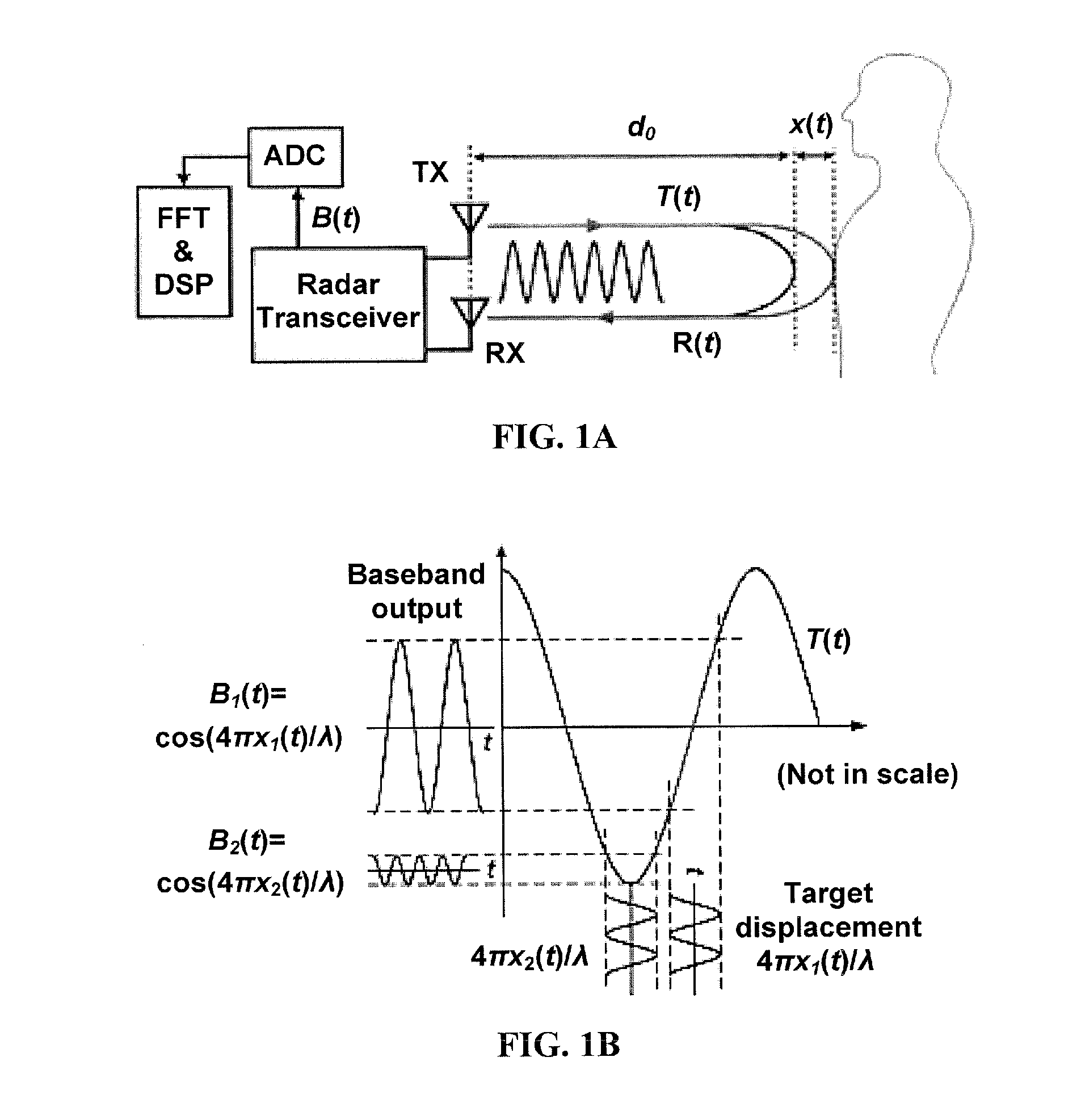
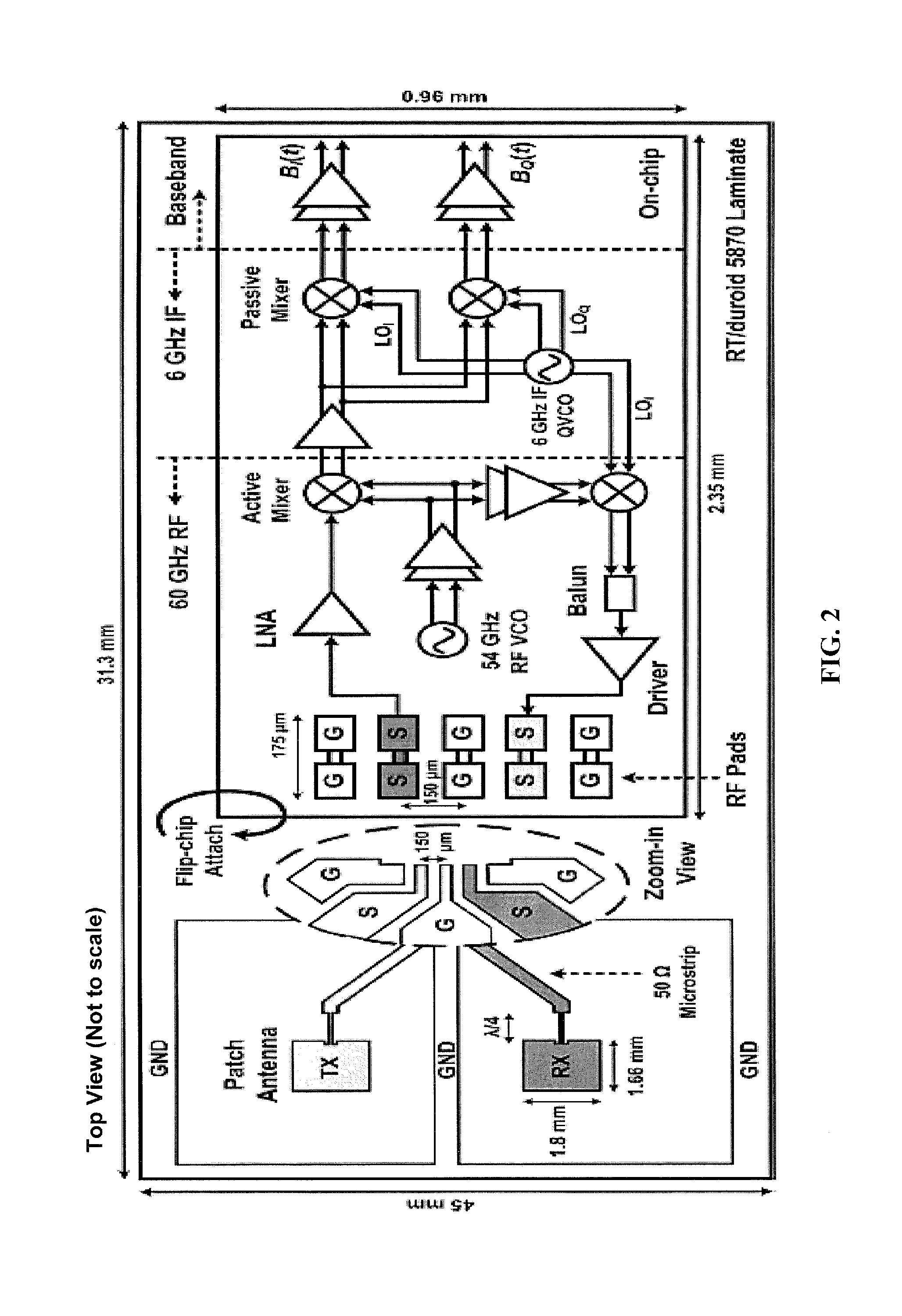
[0034]Embodiments of the subject method and apparatus can increase the accuracy of non-contact vital sign and vibration detection when the target displacement is comparable to the radar wavelength. Vital signs that can be detected include a frequency of respiration and a heart rate. Such vital signs can be detected for a human, or an animal that is not a human, such as a dog, a cat, a horse, or other animal. As a result, a 60-GHz Doppler radar system, for example, can be used for healthcare, biomedical sensors, and vibration / security monitoring in various environments. The antenna and component sizes, which are inversely proportional to wavelength, can be greatly reduced by using 60-GHz or higher radar frequencies rather than 2.4 GHz, 5.8 GHz, or 24 GHz systems. In addition, if the radar chip is implemented in a low-cost Complementary Metal-Oxide-Semiconductor (CMOS) process, the radar system including antennas can be easily integrated into popular smartphones and tablet devices. Ac...


PUM


Abstract

Method and apparatus for detecting a movement, such as two or more periodic vibrations, of a target, by sending a radar signal, e.g., near 60 GHz, at the target and processing the signal reflected by the target. One or more components of the movement can have a predominant frequency, such as a frequency of vibration, and two or more components can have different frequencies and, optionally, different magnitudes. A quadrature receiver processes the received signal to produce a base band output signal having in-phase (I) and quadrature-phase (Q) outputs. The in-phase (I) and quadrature-phase (Q) outputs are cross-referenced and real target movement frequency recovered directly in the time domain. System nonlinearity, which does not occur simultaneously on the I and Q channels, is identified and removed. Radar signals having wavelengths near one or more of the target movement magnitudes can be used.

Description

CROSS-REFERENCE TO RELATED APPLICATIONS[0001]The present application claims the benefit of U.S. Provisional Application Ser. No. 61 / 949,136, filed Mar. 6, 2014, and also claims the benefit of U.S. Provisional Application Ser. No. 61 / 944,428, filed Feb. 25, 2014, both of which are hereby incorporated by reference herein in their entirety, including any figures, tables, or drawings.BACKGROUND OF INVENTION[0002]Doppler radar systems operating at Industrial, Scientific, and Medical (ISM) bands near 2.4 GHz, 5.8 GHz, and 24 GHz have been proven to be effective in non-contact vital sign and vibration detection. Recent research has shown the use of higher radar frequencies (shorter wavelength λ) near 60-GHz ISM band provide a larger system demodulation gain to distinguish small displacements at a longer distance. The use of such higher radar frequencies also helps achieve a highly compact and integrated system, as the antenna size and component sizes are reduced. However, the respiratory c...

Claims


Application Information

Patent Timeline
IPC IPC(8): G01S7/41A61B5/0205A61B5/00G01S13/02
CPCG01S7/41G01S13/02A61B5/0816A61B5/7257A61B5/024A61B5/0205A61B5/05G01S13/50
Inventor LIN, JENSHANKAO, TE-YU
Owner UNIV OF FLORIDA RES FOUNDATION INC
Why Eureka
Try Eureka