

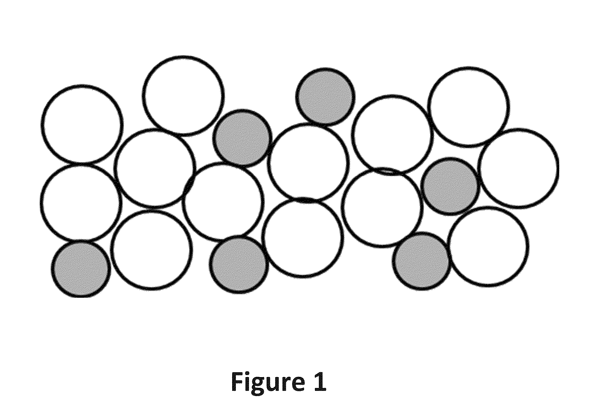
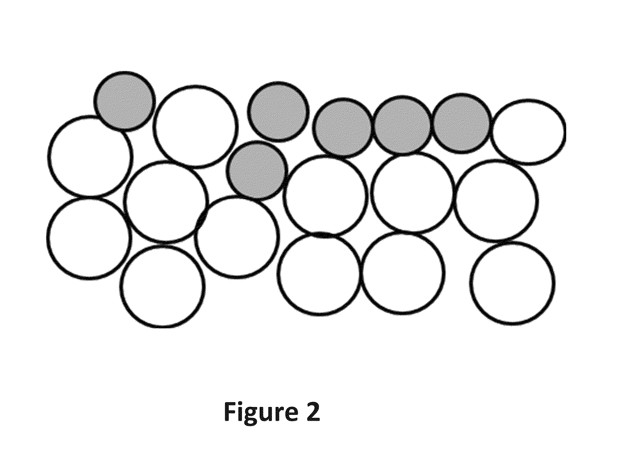
Hybrid electrodes with both intercalation and conversion materials
a technology of hybrid electrodes and conversion materials, applied in the direction of electric/dynamo-electric converter starters, electric vehicles, non-aqueous electrolytes, etc., can solve the problems of not being widely adopted for automotive applications, many conventional rechargeable batteries are not insufficient in at least one of these respects, and unable to meet current and future automotive demands
- Summary
- Abstract
- Description
- Claims
- Application Information
AI Technical Summary
Benefits of technology
Problems solved by technology
Method used
Image

Examples
example 1
Positive Electrode Preparation
[0111]Positive electrodes were prepared by mixing and milling either crystalline FeF3 or an 80:20 w / w mixture of crystalline iron trifluoride (i.e., FeF3) and lithium titanate (LTO) with carbon (C65 Conductive Carbon Black) and an Ethylene Propylene Rubber binder (EPR). These positive electrodes were disposed onto a liquid electrolyte including celgard membrane which was disposed on and contacting a Li-metal anode. The celgard separator contained the liquid electrolyte and physically separated the positive and negative electrodes. The liquid electrolyte included ethylene carbonate (EC) dimethylcarbonate (DMC) solvents in a 50:50 v / v (EC:DMC) ratio with 1M LiPF6 salt. In some examples, the electrochemical cells included only FeF3 as the positive electrode active material. In some other examples, the electrochemical cells included both FeF3 and LTO in an 80:20 w / w ratio as the positive electrode active material.
example 2
Electrochemical Testing of Hybrid Positive Electrodes with Comparison to Positive Electrodes Having Conversion Chemistry Active Materials
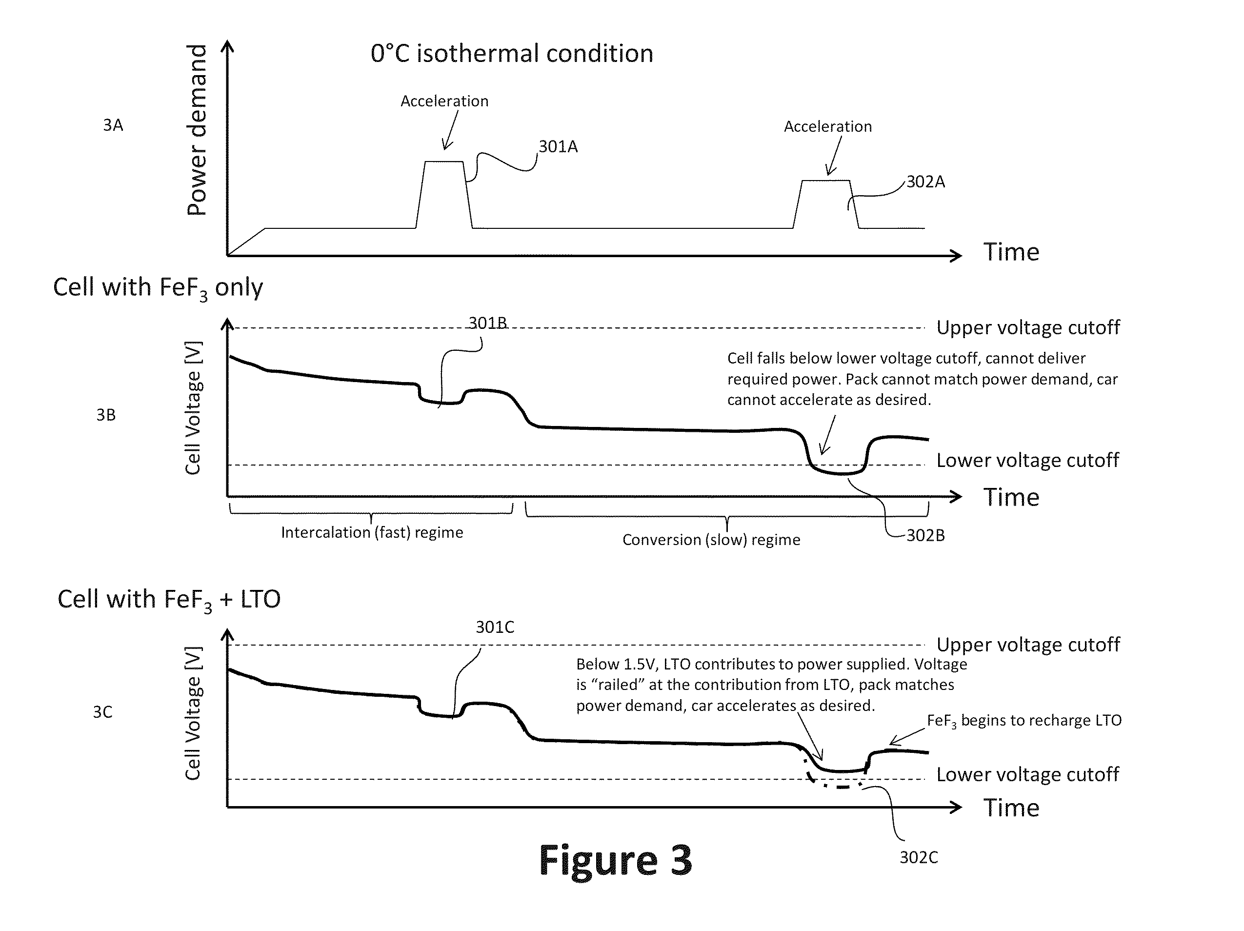
[0112]FIG. 11 shows a high rate discharge initially after assembling the electrochemical cell (i.e., 0th discharge). The discharge was run at C / 10 rate and at 50° C. The plateau at 1.6V in the LTO-including sample shows that the positive electrode with both FeF3 and LTO took a longer time during discharge to reach the 1.5V floor. This example demonstrates that LTO, with a lower operating voltage above the lowest conversion voltage for FeF3 “railed,” or prevented, the electrochemical cell from dropping to 1.5V as soon as it would have in the absence of LTO (i.e., in the electrochemical cell having only FeF3).
[0113]FIG. 12 shows the subsequent charging of the electrochemical cells used in the experiment to generate the data in FIG. 11. The initial plateau at 1.6V in the LTO-including sample shows that the positive electrode with both FeF3 and LTO beg...
example 3
Electrochemical Testing of Hybrid Positive Electrodes with Comparison to Positive Electrodes Having Conversion Chemistry Active Materials
[0114]Electrochemical cells were prepared according to Example 1. These electrochemical cells were analyzed at 50° C. using the following pulse cycle: An C / 10 rate continuous discharge pulse, followed by a rest to allow the cell voltage to equilibrate, and 1 minute current pulses of C / 5, C / 3, and C / 2, each with a five (5) minute rest period in between the discharge pulse. The cell Voltage (V v. Li) as a function of Run Time (s) was observed and recorded as FIGS. 13-18. The control samples only included FeF3 as the positive electrode active material. The LTO samples included both FeF3 and LTO (lithium titanate) in an 80:20 w / w ratio.
[0115]FIG. 13 shows the discharge voltage versus time near the end of a discharge for two representative control cells with 100% conversion chemistry, FeF3, cathodes compared to two representative cells with a hybrid cat...
PUM
| Property | Measurement | Unit |
|---|---|---|
| voltage | aaaaa | aaaaa |
| cell voltage | aaaaa | aaaaa |
| operating temperature | aaaaa | aaaaa |
Abstract
Description
Claims
Application Information