Method for cleaning a waste water vessel for the waste water industry

Inactive Publication Date: 2015-09-10
GREEN CHANNEL
View PDF6 Cites 1 Cited by
  • Summary
  • Abstract
  • Description
  • Claims
  • Application Information

AI Technical Summary

Benefits of technology

[0027]The step of adding an inhibitor to the waste water vessel may cause the pH of a mixture comprising the first reagent and second reagent to increase, i.e. for the acidity to lessen, or for the acidity to approach 7.0. That is, when the inhibitor is added to the waste water vessel, the pH of the mixture comprising the inhibitor, the reagents, and the activator (if present) will have a less acidic pH than the mixture before the inhibitor is added. It has been found that in some embodiments the speed of the reaction can be controlled by changing the PH and in particular by decreasing the pH of the mixture, the reaction can be slowed down, causing heat to be generated more slowly.
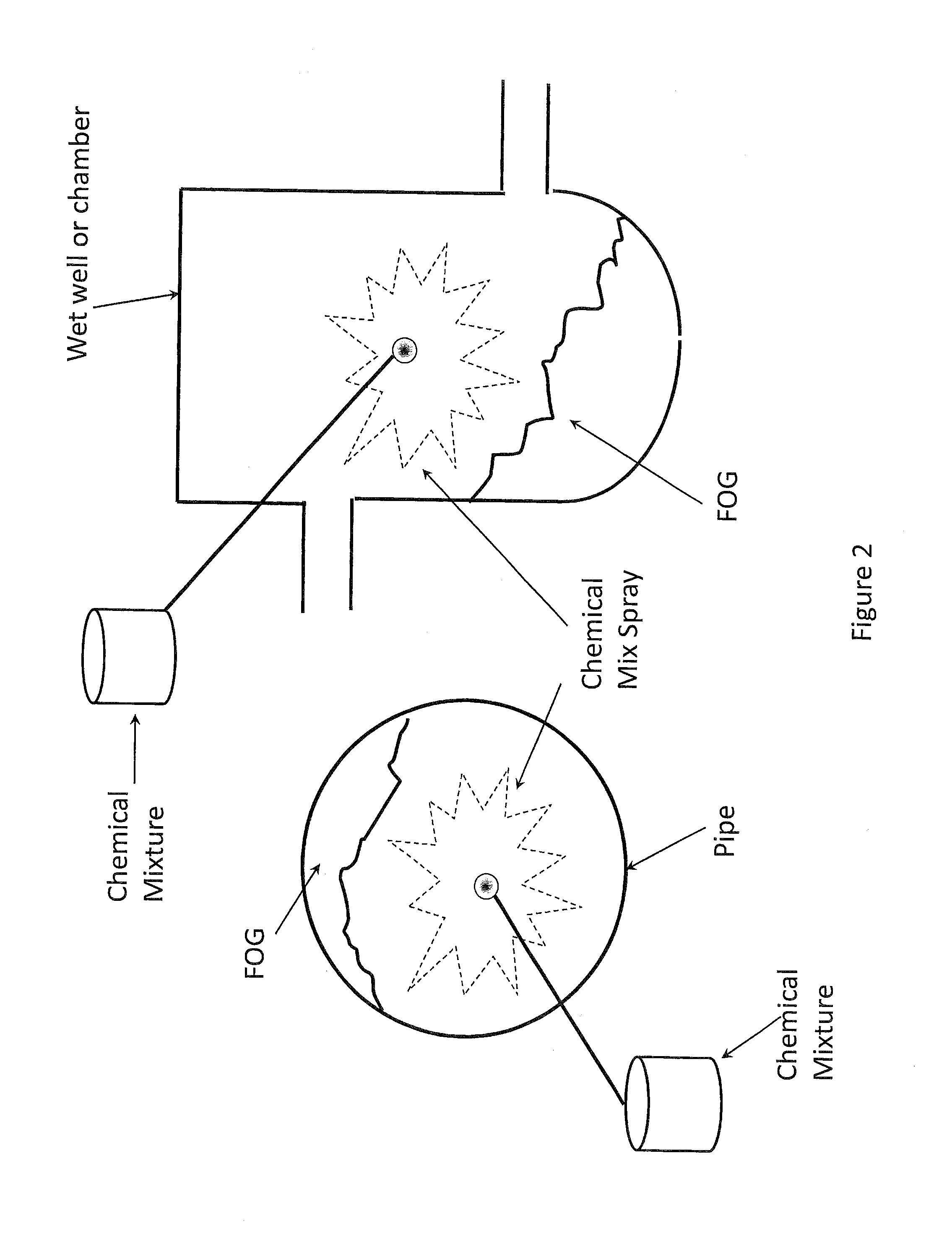
[0028]In some embodiments, a mixture comprising the first reagent and activator is sprayed onto a wall of the waste water vessel. After having sprayed such a mixture onto walls of the waste water vessel (including on the FOG deposits of the waste water vessel), the reaction can be initiated by subsequently spraying the second reag

Problems solved by technology

In the waste water industry, it is common for waste water vessels to become clogged with deposits comprising waste fats, oils or grease.
Typically, these deposits are caused as a result of high temperature, liquid FOG being inappropriately disposed of.
Over time, these deposits grow and impede the passage of waste water through the waste water vessel.
Once the deposits have reached such an extent that the effectiveness of the waste water vessel has become unacceptable to its operators, it becomes necessary to clear the waste water vessel of the deposits.
This process is expensive, time consuming, unpleasant and potentially dangerous due to the presence of sewer gases.
These gases, which include hydrogen sulphide, sulphur dioxide and methane, may be toxic and may have the potential to cause explosions and/or fires.
As a result, there is a limited window of opportu

Method used


Image

  • Method for cleaning a waste water vessel for the waste water industry
  • Method for cleaning a waste water vessel for the waste water industry
  • Method for cleaning a waste water vessel for the waste water industry

Examples


Embodiment Construction

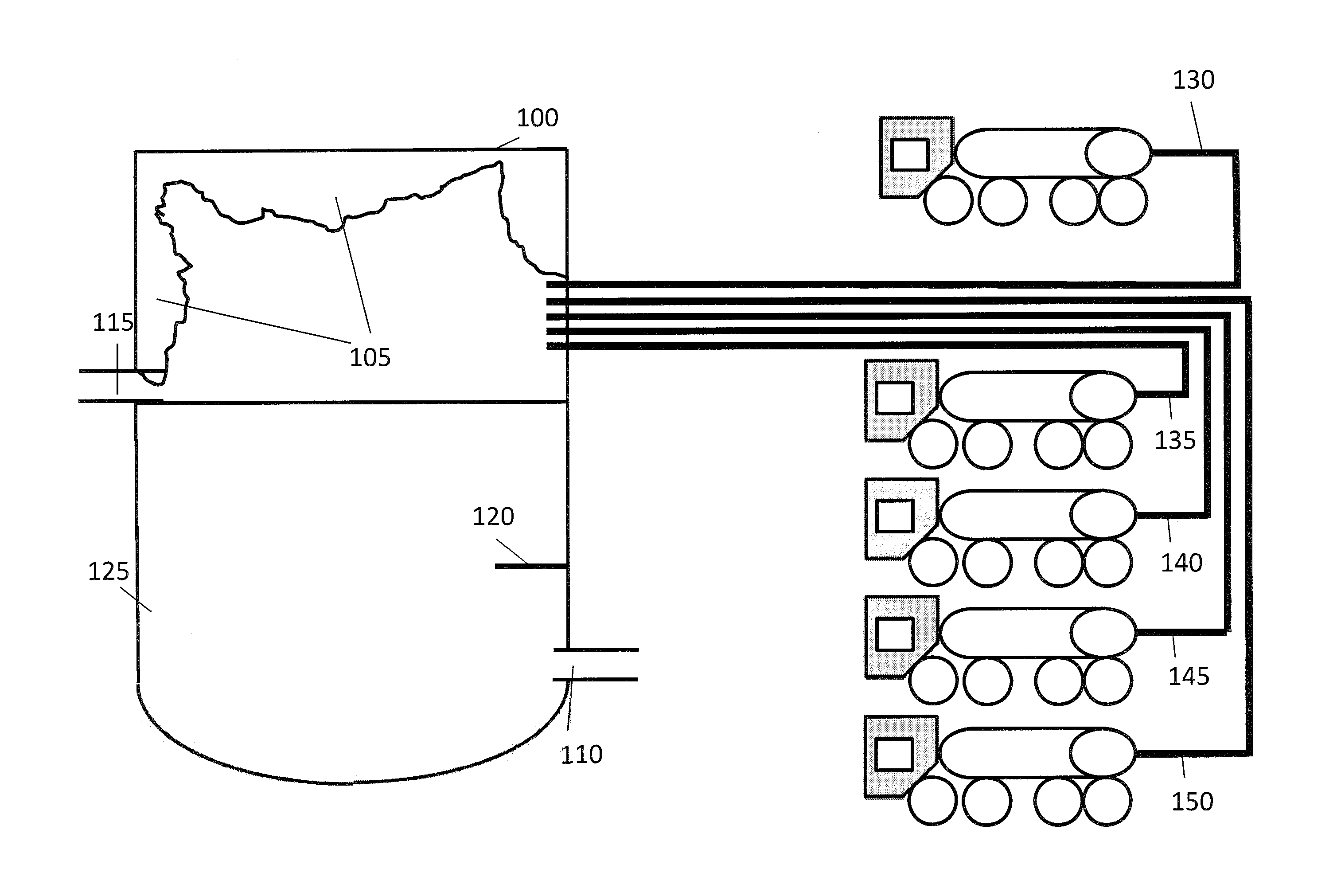
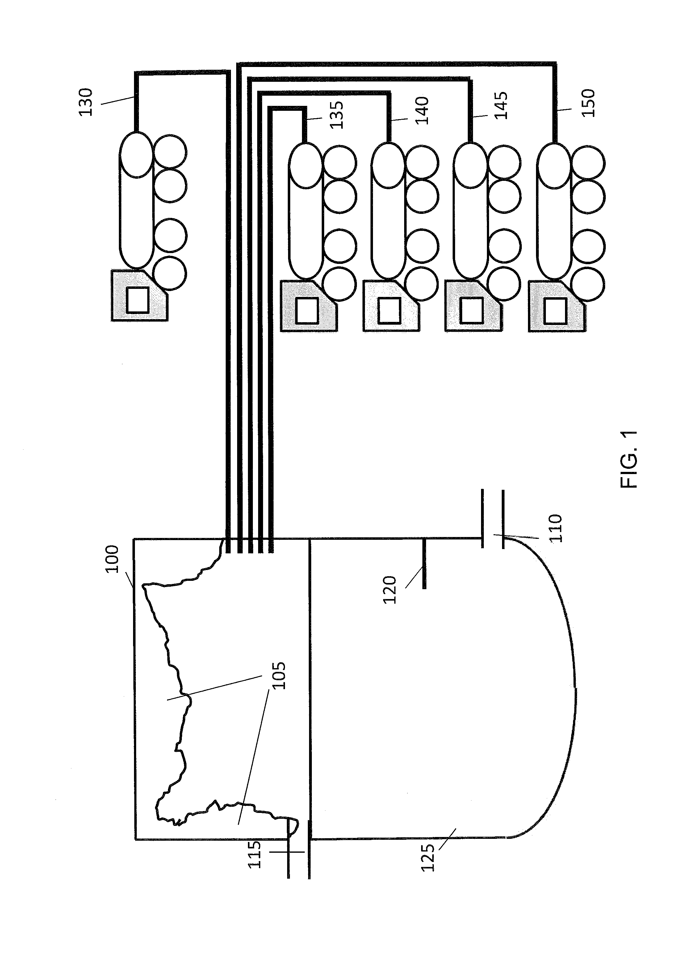
[0047]FIG. 1 is a diagram schematically illustrating a cross section of a waste water vessel to be cleaned in accordance with one embodiment. In this embodiment the waste water vessel 100 is a settling tank in a waste water treatment plant. As shown in FIG. 1, the waste water vessel 100 contains an inlet pipe 110, from which waste water 125 enters the vessel and an outlet pipe 115 located at the top of the waste water vessel 100. Waste water 125 enters the vessel via pipe 110 and is allowed to settle, causing particles and other detritus (not shown) to sink to the bottom of the tank. As waste water 125 enters the tank, the level of the waste water 125 rises, until it reaches the level of the outlet pipe 115 at which point, the top layer of waste water 125 exits via outlet pipe 115. The waste water 125 may comprise fats, oils and grease which have been inappropriately disposed of These substances may initially enter the waste water vessel 100 in a liquid state. However, as they cool,...


PUM


Abstract

A method is provided for cleaning a waste water vessel (100) for the waste water industry. The method comprises adding (130) a first quantity of a first reagent to the waste water vessel (100); and adding (135) a second quantity of a second reagent to the waste water vessel (100), said first and second reagents being reagents that react together in an exothermic reaction the products of which comprise sodium chloride and nitrogen, the heat generated from the exothermic reaction being sufficient to cause solidified fats, oil or grease deposits in the waste water vessel (100) to melt.

Description

FIELD OF THE INVENTION[0001]The present invention relates to a method for cleaning a waste water vessel for the waste water industry.BACKGROUND OF THE INVENTION[0002]In the waste water industry, it is common for waste water vessels to become clogged with deposits comprising waste fats, oils or grease. The term FOG is used herein and is recognised in the industry, as describing compositions including fat, oil, and / or grease.[0003]Typically, these deposits are caused as a result of high temperature, liquid FOG being inappropriately disposed of. After being disposed of, the FOG begins to cool down. Once the temperature of the FOG drops below the melting point, it solidifies and forms deposits within the waste water vessel. Over time, these deposits grow and impede the passage of waste water through the waste water vessel. The effectiveness of the waste water vessel is thereby reduced.[0004]Once the deposits have reached such an extent that the effectiveness of the waste water vessel ha...

Claims


Application Information

Patent Timeline
IPC IPC(8): B08B9/08B08B9/093
CPCB08B9/0856B08B9/08B08B9/093B08B9/027B08B9/0495C02F11/18B08B3/08C02F11/00C09K5/16
Inventor PALMER, CYRILROE, ASHLEY EDWIN
Owner GREEN CHANNEL
Why Eureka
Try Eureka