Optical fiber fabrication method

a technology of optical fiber and manufacturing method, which is applied in the field of optical fiber manufacturing method, can solve the problems of increasing the loss of optical fiber when the optical fiber is installed, reducing the productivity reducing the efficiency of optical fiber manufacturing, so as to achieve the effect of low fictive temperature and high productivity

Inactive Publication Date: 2015-09-10
SUMITOMO ELECTRIC IND LTD
View PDF9 Cites 22 Cited by
  • Summary
  • Abstract
  • Description
  • Claims
  • Application Information

AI Technical Summary

Benefits of technology

[0013]According to the present invention, it is possible to sufficiently lower a fictive temperature and manufacture a low-loss optical fiber with high productivity.

Problems solved by technology

The loss increases when the optical fiber is installed and used in a cable.
However, the PSCF is generally expensive and there is a demand for low-loss, low-nonlinearity optical fibers which are inexpensive.
Conventional slow-cooling techniques do not optimize the temperature history of the optical fiber in a predetermined range.
As a result, such conventional slow-cooling techniques may not efficiently reduce attenuation in the optical fiber, and may degrade productivity, because a heating furnace for slow cooling may become unnecessarily long, or a drawing speed may become slow to ensure a long slow-cooling time.

Method used


Image

  • Optical fiber fabrication method
  • Optical fiber fabrication method
  • Optical fiber fabrication method

Examples


Embodiment Construction

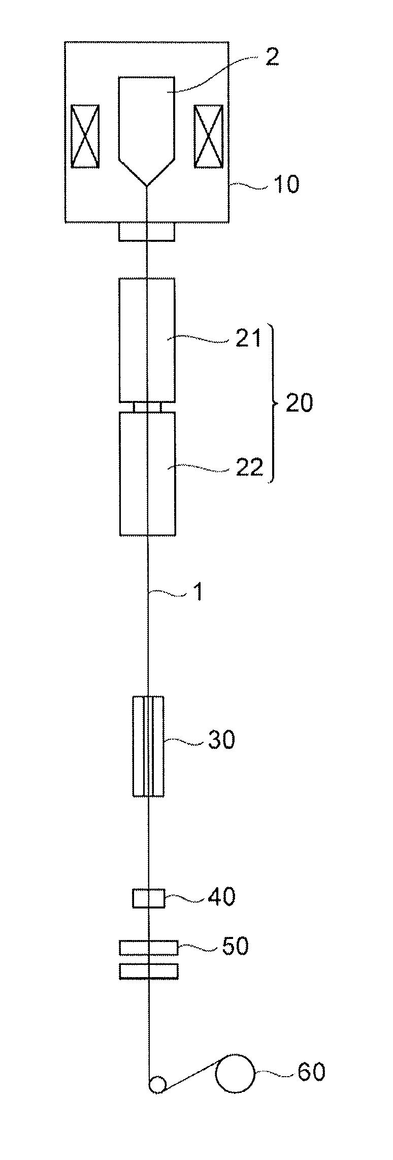
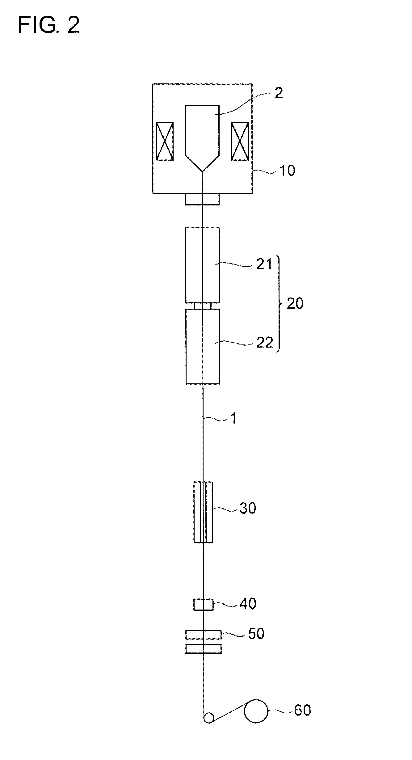
[0020]Embodiments for carrying out the present invention will now be described in detail with reference to the attached drawings. In the description of the drawings, the same elements are given with the identical reference numerals, and redundant description will be omitted.

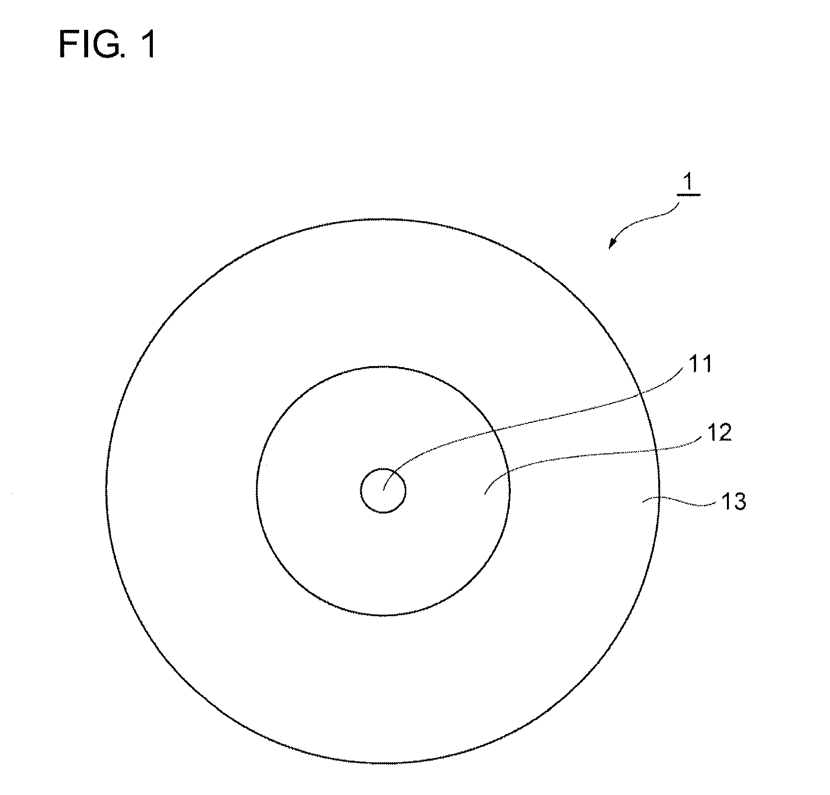
[0021]FIG. 1 is a cross-sectional view of an optical fiber 1 according to the present invention. The optical fiber 1 is a silica-based optical fiber and includes a center core 11 having a center axis, an optical cladding 12 surrounding the center core 11, and a jacket 13 surrounding the optical cladding 12.

[0022]Relative refractive index differences of the center core 11 and the jacket 13 are respectively described relative to the refractive index of the optical cladding 12. The refractive index of the center core 11 is described as an equivalent step index (ESI). A diameter at which a differential value of radial change in refractive index at the boundary between the optical cladding 12 and the jacket 13 is larg...


PUM

PropertyMeasurementUnit
fictive temperatureaaaaaaaaaa
temperatureaaaaaaaaaa

Abstract

An optical fiber manufacturing method includes a drawing step and a slow cooling step. In the slow cooling step, an optical fiber passes through a heating furnace having a temperature which is set such that in at least 70% of a region from a first position at which a glass outer diameter of the optical fiber becomes less than 500% of a final outer diameter to a second position at which a temperature T of the optical fiber becomes 1400° C., an actual temperature of the optical fiber is within ±100° C. of a target temperature Tt(n) for each position n. The target temperature Tt(n) is a temperature at which a fictive temperature Tf(n+1) of a core at a position n+1 determined by calculation using the recurrence formula “Tf(n+1)=T(n)+(Tf(n)−T(n))exp(−Δt(T(n)))” starting from a fictive temperature Tf(0) of the optical fiber at the first position n=0 is lowest.

Description

TECHNICAL FIELD[0001]The present invention relates to an optical fiber manufacturing method.BACKGROUND ART[0002]For high-speed optical communication which allows a transmission rate of 100 Gbit / s or more, a high optical signal-to-noise ratio (OSNR) is required. Optical fibers used as optical transmission lines are increasingly demanded to be low-loss, low-nonlinearity optical fibers. Nonlinearity of an optical fiber is in proportion to n2 / Aeff, where n2 is a nonlinear refractive index of the optical fiber and Aeff is an effective area of the optical fiber. The larger the effective area Aeff, the more it is possible to reduce concentration of optical power on the core and thus to reduce nonlinearity. A standard single-mode optical fiber compliant with ITU-T G. 652 has an effective area Aeff of about 80 μm2 at a wavelength of 1550 nm. It is preferable, however, that the effective area Aeff of a low-nonlinearity optical fiber be in the range from 110 μm2 to 180 μm2.[0003]An enlarged ef...

Claims


Application Information

Patent Timeline
Patent Type & Authority Applications(United States)
IPC IPC(8): C03B37/027C03B37/025G02B6/10
CPCC03B37/02718G02B6/10C03B2203/22C03B2205/72C03B37/0253C03B37/02727C03B2205/56C03B2201/31C03C25/002C03C25/607C03B2205/55
Inventor NAKANISHI, TETSUYAKONISHI, TATSUYAKUWAHARA, KAZUYA
Owner SUMITOMO ELECTRIC IND LTD
Why Eureka
Try Eureka