
Four-Cycle Internal Combustion Engine with Pre-Stage Cooled Compression

a technology of internal combustion engine and compression, which is applied in the direction of combustion engine, machine/engine, charge feed system, etc., can solve the problems of reducing engine life, affecting efficiency, and reducing the efficiency of a standard four-cycle petroleum internal combustion engine with respect to compression ratio and pre-ignition compression high pressure temperatures, so as to achieve a slightly better efficiency gain, higher pre-ignition compression, and higher compression ratios

Active Publication Date: 2015-09-10
KRISTANI FILIP
View PDF4 Cites 12 Cited by
  • Summary
  • Abstract
  • Description
  • Claims
  • Application Information

AI Technical Summary

Benefits of technology

The present invention relates to a method for improving engine efficiency by increasing the compression ratio of the air / fuel mixture before ignition. This is achieved by using a pre-stage compressor to compress the intake air and a heat-exchanger to cool the compressed air before it enters the combustion cylinder. By reducing the intake air temperature, the pre-ignition temperature of the air / fuel mixture is lowered, allowing for higher compression ratios and much higher power output and efficiency, regardless of ambient temperature changes. The invention optimizes engine efficiency by maximizing the pressure drop during the expansion cycle and keeping the temperature of the air / fuel mixture constant during ignition.

Problems solved by technology

The efficiency of a standard four-cycle petroleum internal combustion engine is limited with respect to compression ratio and pre-ignition compression high pressure temperatures.
This is because of the need to avoid pre-ignition temperatures close to the fuel's auto-ignition temperature threshold, beyond which the knocking effect will impair efficiency and reduce engine life.
These temperature and pressure constraints of the standard four-cycle engine design not only reduce engine efficiency, but they also result in larger and heavier engines and impose restrictions on the type of fuel that these engines can combust without knocking

Method used


Image

  • Four-Cycle Internal Combustion Engine with Pre-Stage Cooled Compression
  • Four-Cycle Internal Combustion Engine with Pre-Stage Cooled Compression
  • Four-Cycle Internal Combustion Engine with Pre-Stage Cooled Compression

Examples


first embodiment

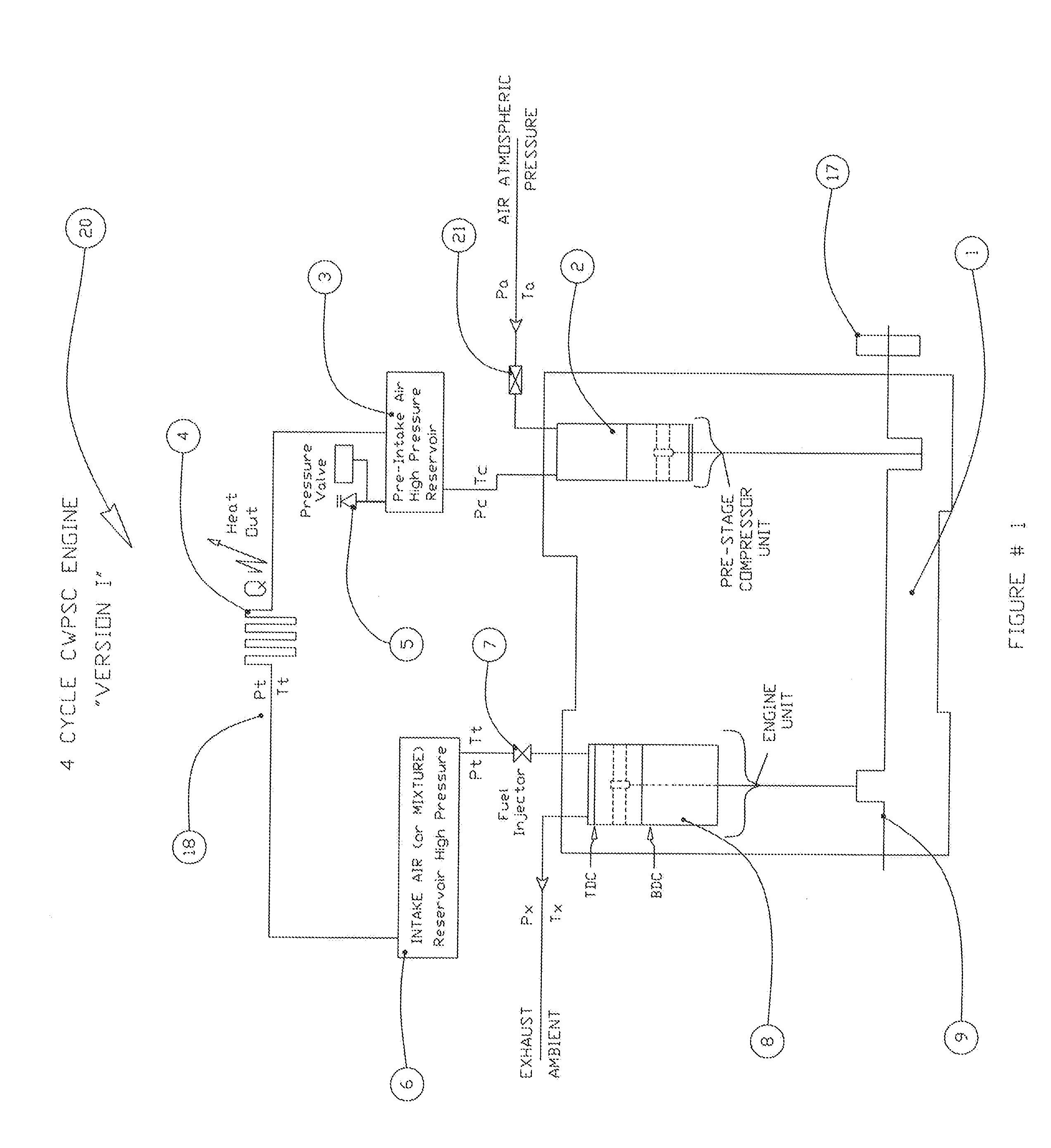
[0053]Referring to FIG. 1, it schematically depicts an exemplary single-cylinder four-cycle internal combustion engine with pre-cooled compression 20, referred to as “Version I”. The engine block 1 comprises a pre-stage compressor 2, a combustion cylinder 8, and an air-cooled heat exchanger 4. In this embodiment, the combustion cylinder 8 and the compressor 2 are connected to the same crankshaft 9 and flywheel 17. Due to the four-cycle combustion process 19, the compressor 2 will complete two compression cycles for each complete combustion cycle. Therefore, during each combustion cycle, the compressor 2 will intake and compress a volume of air equal to twice its cylinder volume.

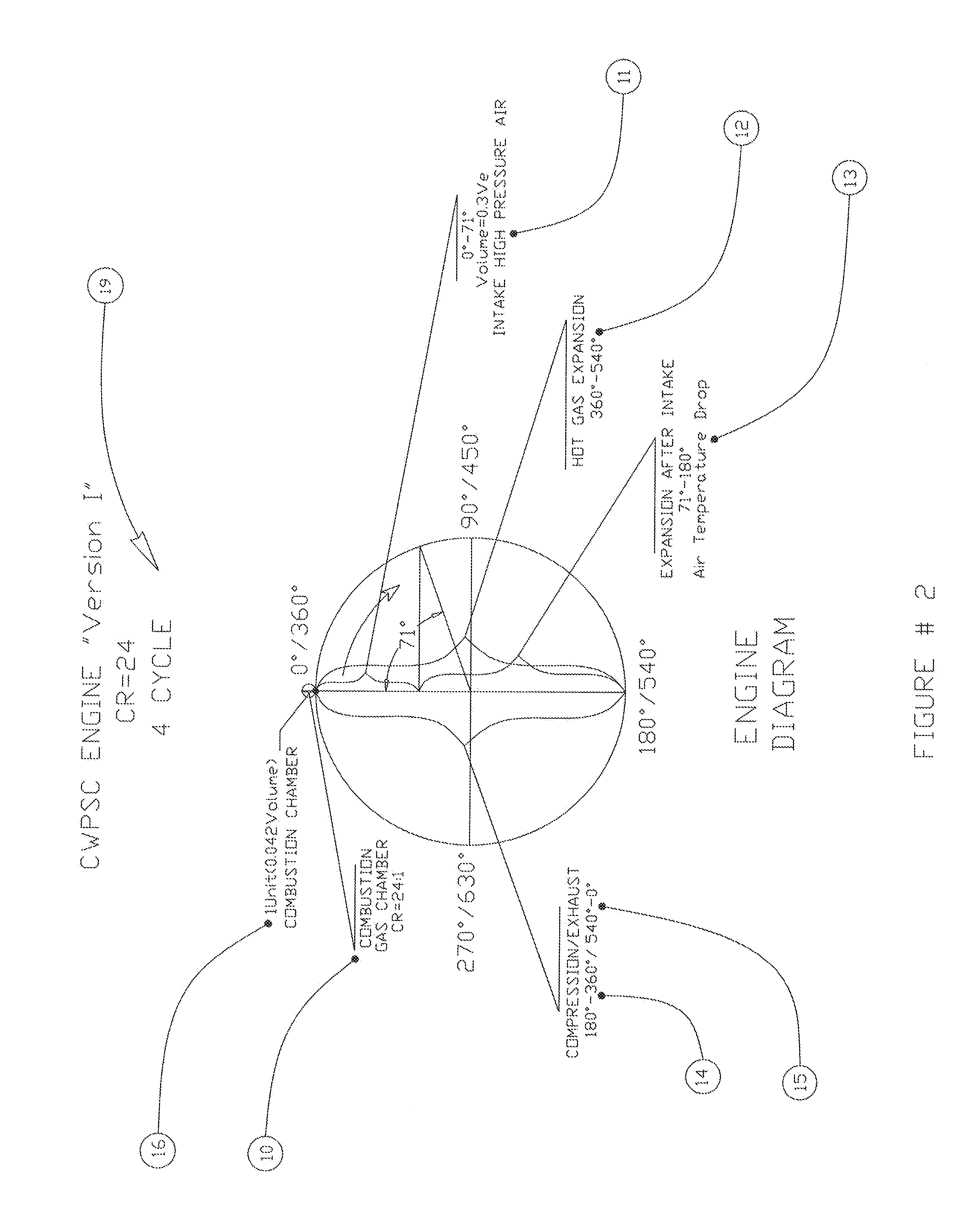
[0054]FIG. 2 is an exemplary four-cycle, single-cylinder combustion process diagram 19, comprising a short intake 11 process (0°-71°), compression 14 (100°-360°), cold air expansion 13 (71°-180°), hot expansion 12 (360°-540°) and exhaust 15 (540°-0°) cycles, with a compression ratio CR 10 of 24:1.

[0055]The re...

exemplary embodiment 22

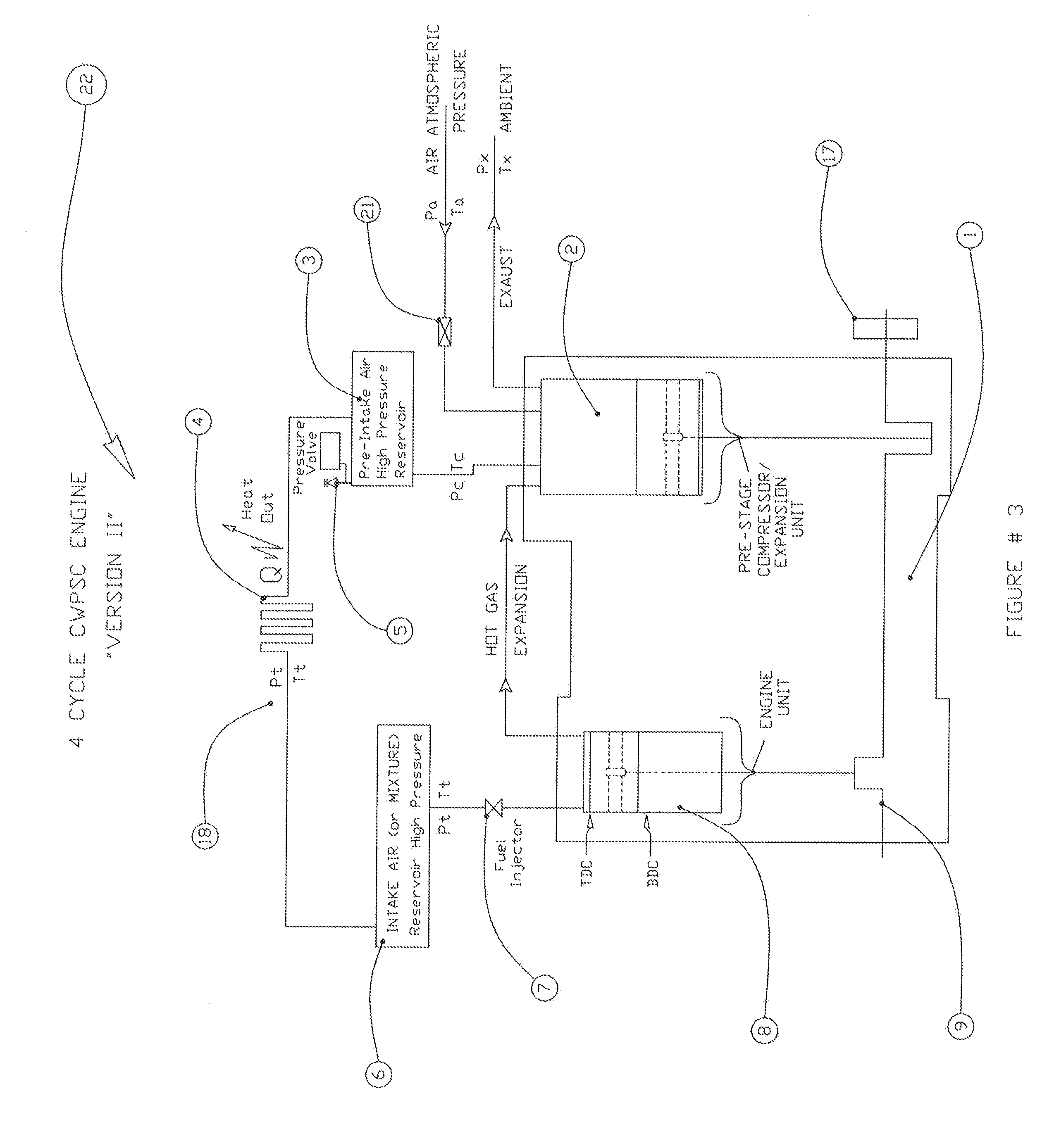
[0087]FIG. 4 illustrates the second exemplary embodiment 22 of a four-cycle internal combustion “Version II” with a cycles diagram 23, showing the compression ratio 10, intake 11, compression 14, expansion 12 and hot gas engine cylinder exit process 15.

[0088]FIG. 5 illustrates the extended expansion captured at compressor cylinder 2, comprising air suction 25, compressor air compression 27, extended hot gas expansion 26 and gas exhaust to ambient 28.

[0089]FIG. 6 illustrates the third exemplary embodiment 32“Version HA” of a four-cycle internal combustion engine having a single combustion cylinder with one-stage pre-cooled compression. This engine works the same as the previous embodiment 22, except that the compressor cylinder 2 may be replaced by a powerful axial compressor 29 or a combination of a compressor cylinder and an axial compressor, and the extended expansion is captured at a powerful turbine 30 which can use the captured energy outright for vehicle movement or store the ...

fourth embodiment

[0104]FIG. 11, is an exemplary four-cycle, single-cylinder combustion process diagram 19 for the fourth embodiment “Version III”. It comprises a normal intake 11 process (180°), compression 14, expansion 12 and exhaust 15 cycles, with a compression ratio CR 10 of 24:1.

[0105]FIGS. 16 and 16A represent the P-V diagram of a CWPSC “Version III” 1 Liter engine with compression ratio CR=24, for the purpose of comparison with a standard engine or a standard “Hypothetical” engine, where:

[0106]a—work spent by the engine on compression=3.275V / cycle,

[0107]b—work gained by engine on expansion=8.81PV / cycle,

[0108]c—work that cannot be captured on exhaust and is lost=1.245PV / cycle,

[0109]d—heat applied to the engine by burning fuel which increases the pressure by 2.5 times,

[0110]e—work balance gained by engine=3.81PV / cycle,

[0111]f—work lost in pre-intake air compression=1.730PV / cycle. Simplified efficiency of this engine is: E =3.81 / 5.055 =75%.

Efficiency Comparisons between “Standard” and “CWPSC” E...


PUM


Abstract

A four-cycle internal combustion engine has a single or multi-stage pre-cooled compression, which allows the temperature and pressure of intake air to the combustion cylinders to be tightly controlled, so that a much higher compression ratio and pre-ignition compression pressure can be achieved without approaching the air / fuel mixture auto-ignition threshold. The minimal threshold pressure of air intake is determined to be >1.8 Bars at sea level and a minimal temperature drop of at least 50° C. at the heat exchanger air cooling radiator. Because this design can effectively regulate and set the maximum pre-ignition temperature of the fuel-air mixture, it can combust virtually any type of liquid hydrocarbon fuel without knocking This four-cycle engine, due to its higher compression ratio, generates power equivalent to or greater than a standard four-cycle engine in a smaller and lighter engine and at a higher efficiency.

Description

REFERENCE TO RELATED APPLICATIONS[0001]This application is a continuation-in-part of application Ser. No. 14 / 200,202, filed Mar. 7, 2014.FIELD OF INVENTION[0002]The present invention relates to the field of internal combustion engines, and more particularly to the field of four-cycle Spark Ignition-Internal Combustion Engines (SI-ICE).BACKGROUND OF THE INVENTION[0003]The efficiency of a standard four-cycle petroleum internal combustion engine is limited with respect to compression ratio and pre-ignition compression high pressure temperatures. This is because of the need to avoid pre-ignition temperatures close to the fuel's auto-ignition temperature threshold, beyond which the knocking effect will impair efficiency and reduce engine life. Since temperature of intake air in a standard four-cycle engine depends on the ambient temperature that can typically vary from −20° C. to +42° C., at full compression inside the engine cylinder, this ambient temperature range translates to a varia...

Claims


Application Information

Patent Timeline
Patent Type & Authority Applications(United States)
IPC IPC(8): F02B29/04
CPCF02B29/0493F02B33/06F02B33/22F02B33/44F02B37/00F02B41/06F02B41/10F02B75/021Y02T10/12
Inventor KRISTANI, FILIP
Owner KRISTANI FILIP
Learn More