Burner, combustion apparatus, water heating apparatus and combustion method

a technology of combustion apparatus and burner, which is applied in the direction of combustion types, lighting and heating apparatus, heating types, etc., can solve the problems of limiting the shape and arrangement of burner ports, unstable combustion on the lean combustion flame side, and inability to form stable flames, etc., to achieve the stability of combustion, improve the function of holding lean flame, and improve the controllability of combustion

Active Publication Date: 2015-09-10
PURPOSE CO LTD
View PDF6 Cites 28 Cited by
  • Summary
  • Abstract
  • Description
  • Claims
  • Application Information

AI Technical Summary

Benefits of technology

[0010]In view of the above problems, a first object of the present invention is to achieve the reduction of CO and NOx, and to improve the function of holding lean flame to achieve the stability of the combust

Problems solved by technology

Thus, there is a problem of limiting shapes and arrangement of burner ports because of shaping of metallic plates.
The lean flame burner ports have a low-level function of holding flame in its vertical and diagonal directi

Method used


Image

  • Burner, combustion apparatus, water heating apparatus and combustion method
  • Burner, combustion apparatus, water heating apparatus and combustion method
  • Burner, combustion apparatus, water heating apparatus and combustion method

Examples


first embodiment

Combustion Apparatus

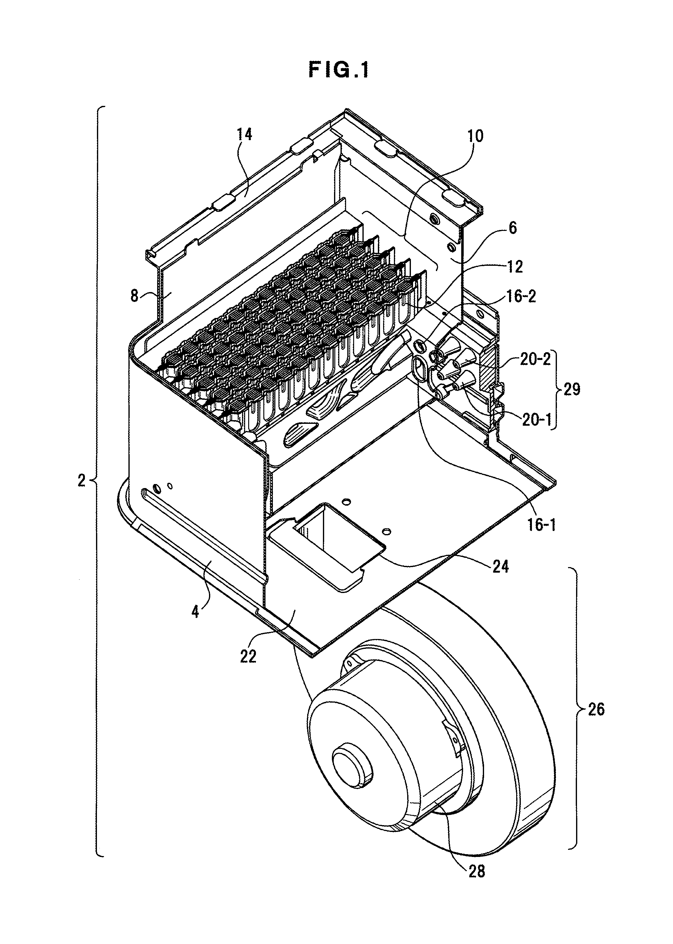
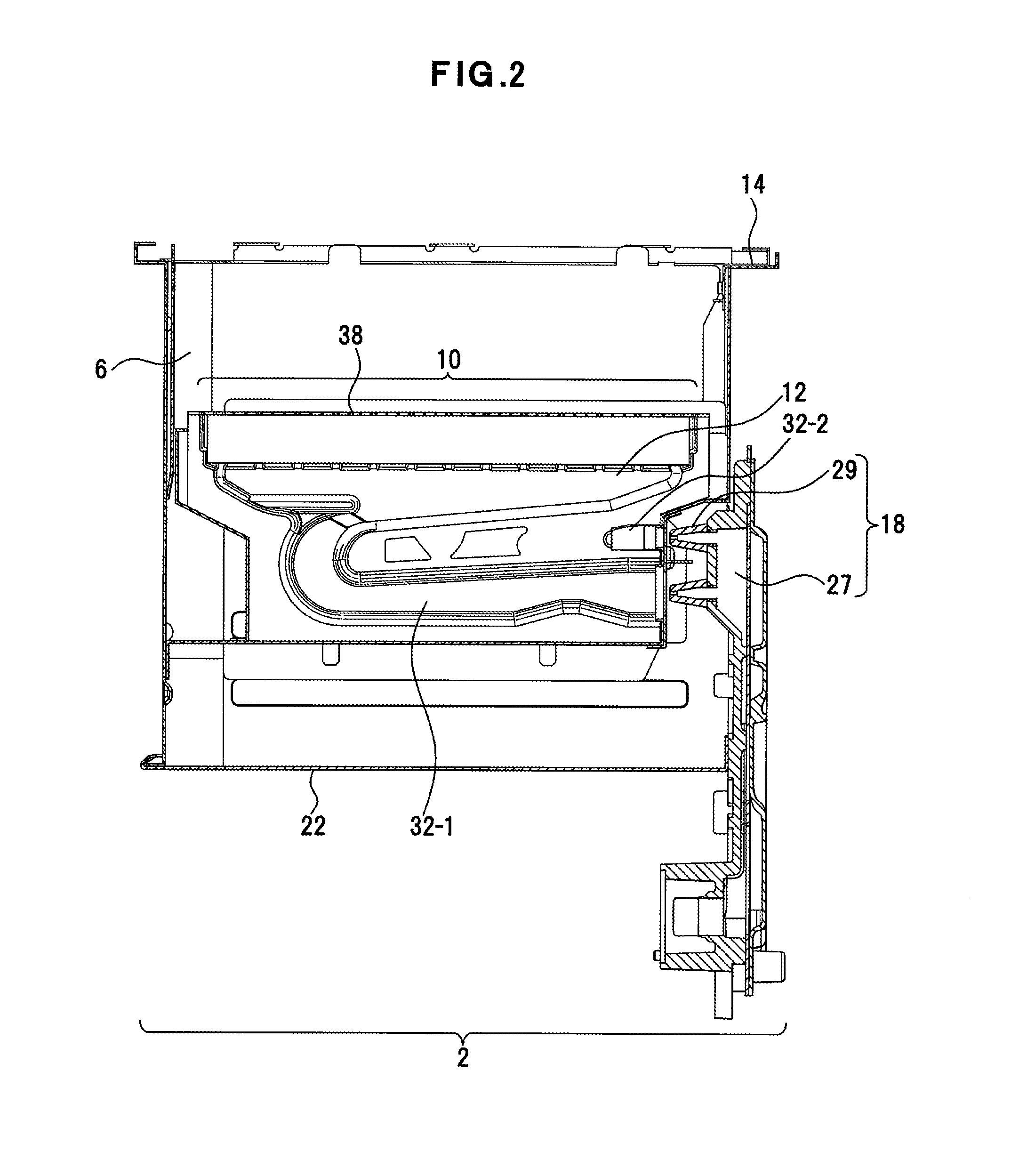
[0036]FIG. 1 depicts a partially cutout combustion apparatus according to the first embodiment. This combustion apparatus 2 is an example of the combustion apparatus of the present invention.

[0037]The combustion apparatus 2 is used as a heat source machine for water heating apparatus and space and water heating apparatus that use fuel gas and the like as fuel. The combustion apparatus 2 includes an apparatus housing 4. A combustion chamber 6 is formed in the apparatus housing 4. The combustion chamber 6 is encompassed by a side wall part 8 of the apparatus housing 4. A burner 10 that combusts fuel gas is disposed in the combustion chamber 6. The burner 10 includes a plurality of burner units 12. For example, a uniform burner port surface is formed over the burner 10.

[0038]A support part 14 is formed on the top of the side wall part 8 as protruding outside along the combustion chamber 6. A heat exchanger, which is not depicted, is disposed on the top surface of th...

second embodiment

Water Heating Apparatus

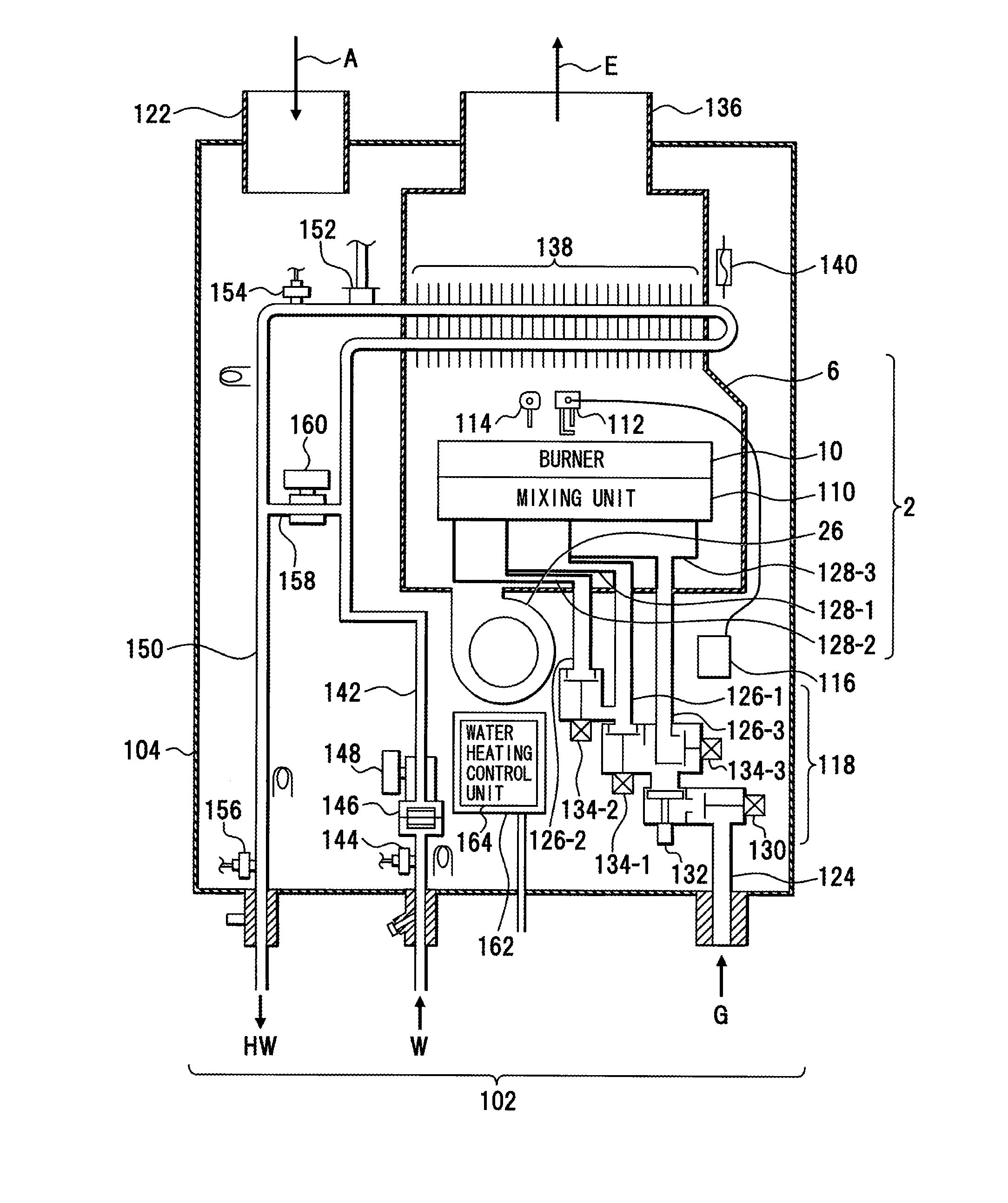
[0134]FIG. 20 depicts an example of the water heating apparatus according to the second embodiment. Structures depicted in drawings, including the structure depicted in FIG. 20, are examples, and such structures do not limit the present invention. This water heating apparatus 102 is an example of using the above described combustion apparatus 2.

[0135]The combustion apparatus 102 includes a housing 104. The housing 104 is equipped with the combustion chamber 6 of the above described combustion apparatus 2. The combustion chamber 6 is also used as a heat exchange housing. The burner 10 that combusts an air-fuel mixture GA is disposed in the combustion chamber 6. The burner 10 combusts the air-fuel mixture GA. The burner 10 is partitioned into a plurality of, for example, five burner units.

[0136]A spark plug 112 as an example of an ignition means and a flame rod 114 as an example of a flame detection means are disposed on the top of the burner 10. An igniter 116 ...


PUM


Abstract

A burner includes a first burner port that generates a first flame, a gap that surrounds the first burner port, and a plurality of second burner ports that are disposed on either side of the gap, the second burner ports generating second flames to hold the first flame. The first burner port combusts a first mixture (lean mixture) to generate the first flame (lean flame). The first mixture includes air more than fuel gas. A gap that surrounds the first burner port is formed. A plurality of the second burner ports are arranged on either side of the gap. The second burner ports combust a second mixture (rich mixture) to generate the second flames (rich flames) and hold the first flame. The air-fuel ratio of the second mixture is smaller than the first mixture.

Description

CROSS-REFERENCE TO RELATED APPLICATIONS[0001]This application is entitled to the benefit of priority of Japanese Patent Application No. 2014-041443, filed on Mar. 4, 2014, the contents of which are hereby incorporated by reference.BACKGROUND OF THE INVENTION[0002]i) Field of the Invention[0003]The present invention relates to combustion technology of burners and the like that combust fuel gas.[0004]ii) Description of the Related Art[0005]Upon gas combustion, air has a high ratio to fuel gas in a lean mixture and a low ratio in a rich mixture. In combustion of lean mixtures, nitrogen oxides (NOx) in combustion exhaust gases can be less but the combustion is not stable. On the contrary, in combustion of rich mixtures, the combustion is stable. It is known in view of their characteristics to improve the stability of combustion together with to reduce NOx, and to hold flame in lean mixtures by flame in rich mixture.[0006]Concerning such gas combustion, it is known that thick flame holes...

Claims


Application Information

Patent Timeline
IPC IPC(8): F24H1/14F23D14/60F23D14/84F23D14/02
CPCF24H1/145F23D14/84F23D14/60F23D14/02F23D14/586F23D14/64F23C2201/20F23C2900/06043F24H9/2035F24D2220/044F24H15/395F24H15/219F24H15/421F24H15/238F24H15/325F24H15/215
Inventor NAITOH, KATSUMISANO, YOSHIAKI
Owner PURPOSE CO LTD
Why Eureka
Try Eureka