
Thickness Determination of Web Product by Mid-infrared Wavelength Scanning Interferometry

a technology of infrared wavelength and thickness determination, applied in the direction of instruments, caliper-like sensors, machines/engines, etc., can solve the problems of measurement drift and inaccuracy, prior art optical techniques are not suitable for all paper products, and achieve better than 1 micron accuracy a challeng

Inactive Publication Date: 2015-09-10
HONEYWELL ASCA INC
View PDF3 Cites 8 Cited by
  • Summary
  • Abstract
  • Description
  • Claims
  • Application Information

AI Technical Summary

Benefits of technology

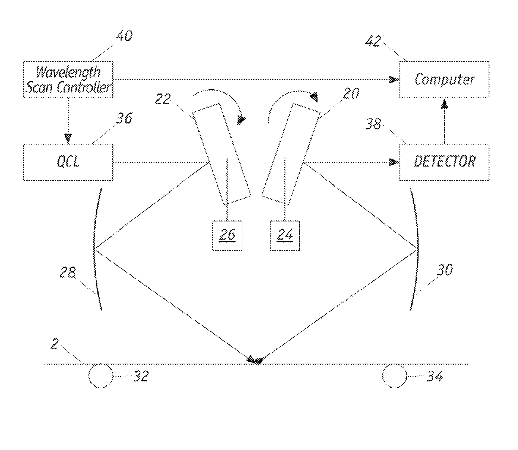
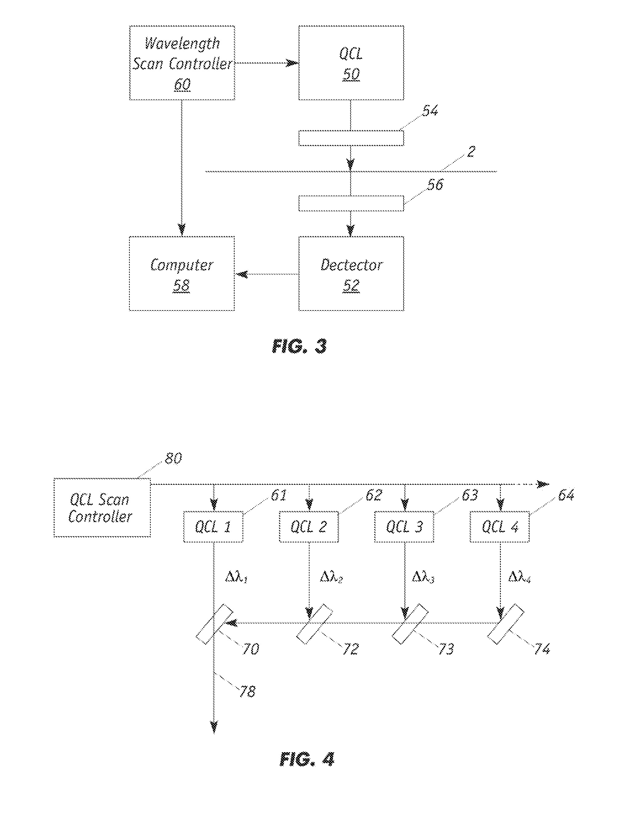
The present invention relates to a method and apparatus for measuring the thickness of a thin film or web. This is achieved through the use of mid-infrared interferometry, which involves directing a laser beam onto a single spot on the surface of the web and analyzing the interference pattern created by the reflected light. The invention provides precise and non-contacting thickness measurement of thin films or webs, with minimal interference from scattering or other factors. The technique uses a monochromatic laser in the mid-infrared range, which is less affected by scattering in the web material. The measurement can be performed in a reflection geometry requiring only one measurement head.

Problems solved by technology

Contacting the web causes a number of issues with the two most significant ones being the marking of the sheet and the accumulating of dirt on the measuring heads, which leads to measurement drift and inaccuracy.
Moreover, prior art optical techniques are not suitable to all paper products because they are very sensitive to the scattering properties of the sheet.
In addition, achieving better than 1 micron accuracy is a challenge as these techniques rely on the difference between two independent distance measurements.
This is difficult to achieve in the paper scanner environment where the measurement heads are exposed to frequent temperature changes and the positions of the paper and heads are subject to constant fluctuations.

Method used


Image

  • Thickness Determination of Web Product by Mid-infrared Wavelength Scanning Interferometry
  • Thickness Determination of Web Product by Mid-infrared Wavelength Scanning Interferometry
  • Thickness Determination of Web Product by Mid-infrared Wavelength Scanning Interferometry

Examples


Embodiment Construction

[0023]The present invention relates to non-contact sensor devices for measuring the thickness of a film, web or sheet. While the sensor will be illustrated in calculating the caliper of paper, it is understood that the sensor cart measure thickness of a variety of flat materials including, for example, coated materials, plastics, fabrics, and the like. The sensor is particularly suited for thickness detection of porous polymers (plastic) made of polyethylene, polypropylene, polyethylene terephthalate, polytetrafluoroethylene or polyvinyl chloride.

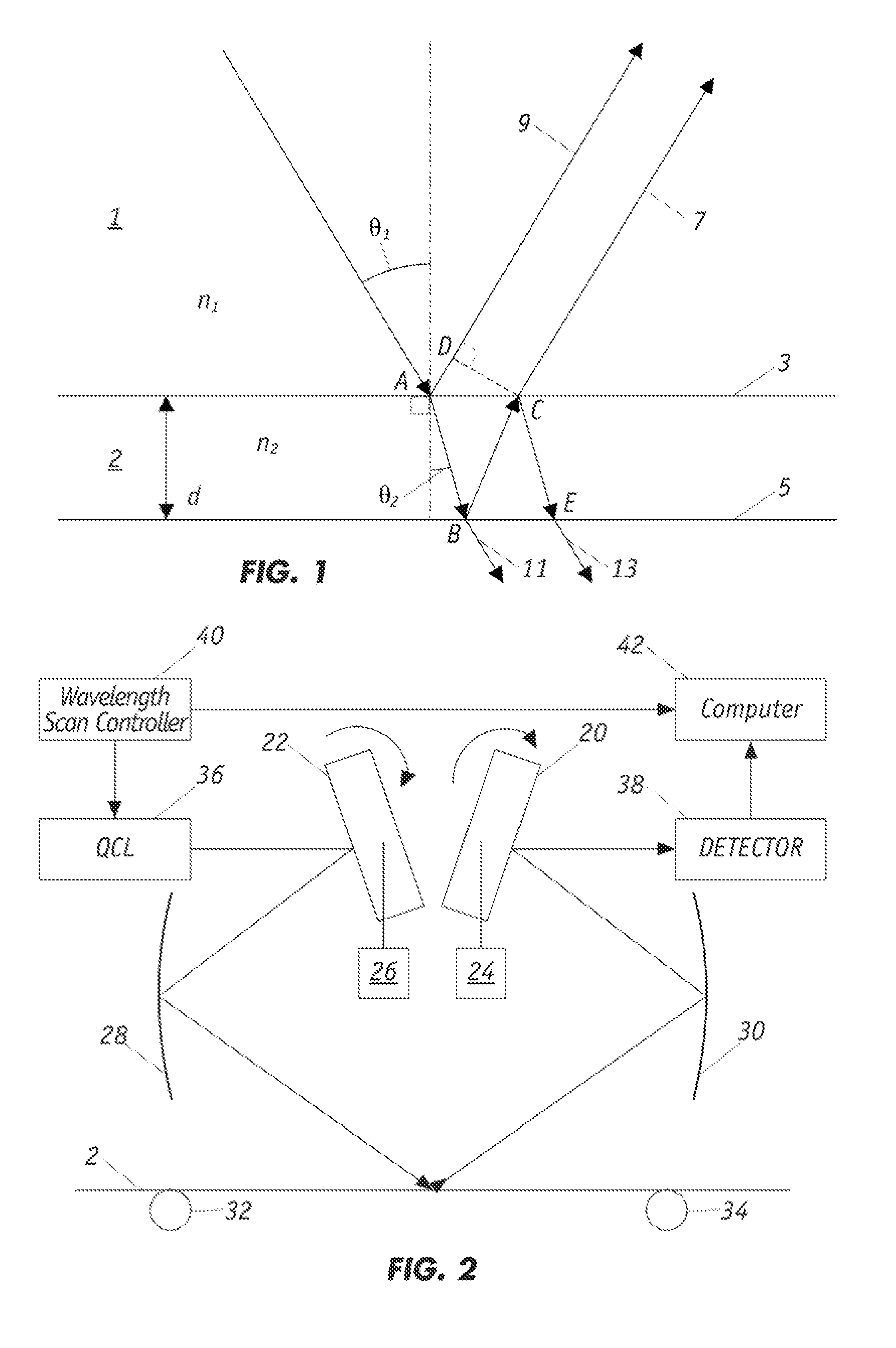
[0024]FIG. 1 illustrates the electromagnetic radiation beam geometry incident, reflected and refracted on a web product 2 of thickness d and having upper and lower sides or planes, plane 3 and plane 5, from which the incident electromagnetic radiation of vacuum wavelength λ0 is reflected (7, 9). In addition, the portion of the incident electromagnetic radiation propagating into the web is refracted since the index of refraction is different...


PUM


Abstract

Non-contacting caliper measurements of free-standing sheets detect mid-IR interferometric fringes created by the reflection of light from the top and bottom surfaces of the sheet. The technique includes directing a laser beam at a selected angle of incidence onto a single spot on the exposed outer surface and scanning the laser beam through a selected wavelength range as the laser beam is directed onto the exposed outer surface and measuring the intensity of an interference pattern that forms from the superposition of radiation that is reflected from the exposed outer surface and from the inner surface. Alternatively, the intensity of an interference pattern formed from the superposition of radiation that is directly transmitted through the web and radiation that is transmitted through the web after internal reflections from the internal surfaces of the web. Thickness can be extracted from the fringe separation in the interference pattern.

Description

FIELD OF THE INVENTION[0001]The present invention relates generally to interferometry techniques for non-contacting thickness or caliper measurements of a moving sheet such as porous polymer and paper and more particularly to methods of detecting mid-IR interferometric fringes created by the reflection of light from the top and bottom surfaces of the sheet and thereafter extracting the thickness from the fringe separation.BACKGROUND OF THE INVENTION[0002]Caliper is one of the most important quality specifications of paper and plastic products. Traditional commercial on-line caliper measurement requires the measuring heads to physically touch the web. Contacting the web causes a number of issues with the two most significant ones being the marking of the sheet and the accumulating of dirt on the measuring heads, which leads to measurement drift and inaccuracy. More advanced techniques make use of laser triangulation or confocal microscopy techniques but they still require a measuring...

Claims


Application Information

Patent Timeline
Patent Type & Authority Applications(United States)
IPC IPC(8): G01B11/06
CPCG01B11/06G01B11/0625G01B2210/46G01B11/0691G01B11/0675G01B9/02017
Inventor HUGHES, MICHAEL KON YEWTIXIER, SEBASTIENSAVARD, STEPHANE
Owner HONEYWELL ASCA INC
Learn More