Method for producing 2d/3d switchable integral imaging liquid crystal cell, and liquid crystal cell

a liquid crystal cell and integral imaging technology, applied in the direction of optics, instruments, adhesives, etc., can solve the problems of inconvenient operation, incompatibility of liquid crystal cells with 2d and 3d displays, and general complexity of methods for producing liquid crystal cells, etc., to achieve simple structure and easy and convenient to obtain

Active Publication Date: 2015-09-10
TCL CHINA STAR OPTOELECTRONICS TECH CO LTD
View PDF3 Cites 0 Cited by
  • Summary
  • Abstract
  • Description
  • Claims
  • Application Information

AI Technical Summary

Benefits of technology

[0003]A technical problem to be solved by the present disclosure is to provide a method for producing a 2D / 3D switchable integral imaging liquid crystal device, which allows switching between the display of a 2D image and display of a 3D image to realize display compatibility of 2D and 3D images in a manner which is easy and convenient to operate.
[0012]Compared with the prior art, the method for producing a 2D / 3D switchable integral imaging liquid crystal cell according to the present disclosure has the following advantages. Through the arrangement of two transparent conductive films, two electrodes are formed by the two transparent conductive films when a voltage is applied. The existence of the grooves on the UV adhesive layer leads to different distances between the two transparent conductive film electrodes, so as to generate electric fields of different intensities between the two electrodes and different refractive indexes of light. As a result, light beams are deflected to different degrees and thus present different states when passing through the liquid crystal cell, and therefore a 3D image is presented. When no voltage is applied, light beams pass through the liquid crystal cell with substantially the same deflection angle, and thus a 2D image is presented. Therefore, switchable displays between 2D and 3D images can be realized through use or non-use of a voltage. In this manner, the purpose that a liquid crystal cell is capable of not only displaying 3D images but also clearly displaying 2D images can be achieved. That is, switchability and display compatibility between 2D and 3D images are realized.
[0013]In one embodiment, the grooves in step 2) are formed as arc-shaped. The arc-shaped grooves can be conveniently imprinted by using a spherical lens array, which is a relatively easy way.
[0018]The liquid crystal cell includes an upper substrate and an opposite lower substrate. A UV adhesive layer having grooves thereon is arranged on an upper surface of the lower substrate. A lower transparent conductive film is arranged on the UV adhesive layer. The grooves are filled with a planarization material on the lower transparent conductive film to form a first plane, and an upper transparent conductive film is arranged on a lower surface of the upper substrate to form a second plane. A liquid crystal layer is arranged between the first plane and the second plane. The liquid crystal cell is of simple structure and easy and convenient to obtain.

Problems solved by technology

Generally, liquid crystal cells in the prior art are incompatible with 2D and 3D displays.
Moreover, methods for producing liquid crystal cells are generally complex and inconvenient to operate.

Method used


Image

  • Method for producing 2d/3d switchable integral imaging liquid crystal cell, and liquid crystal cell
  • Method for producing 2d/3d switchable integral imaging liquid crystal cell, and liquid crystal cell
  • Method for producing 2d/3d switchable integral imaging liquid crystal cell, and liquid crystal cell

Examples


example 1

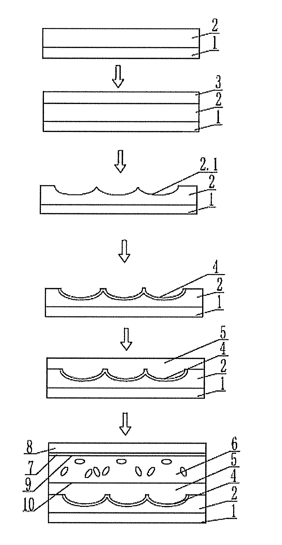
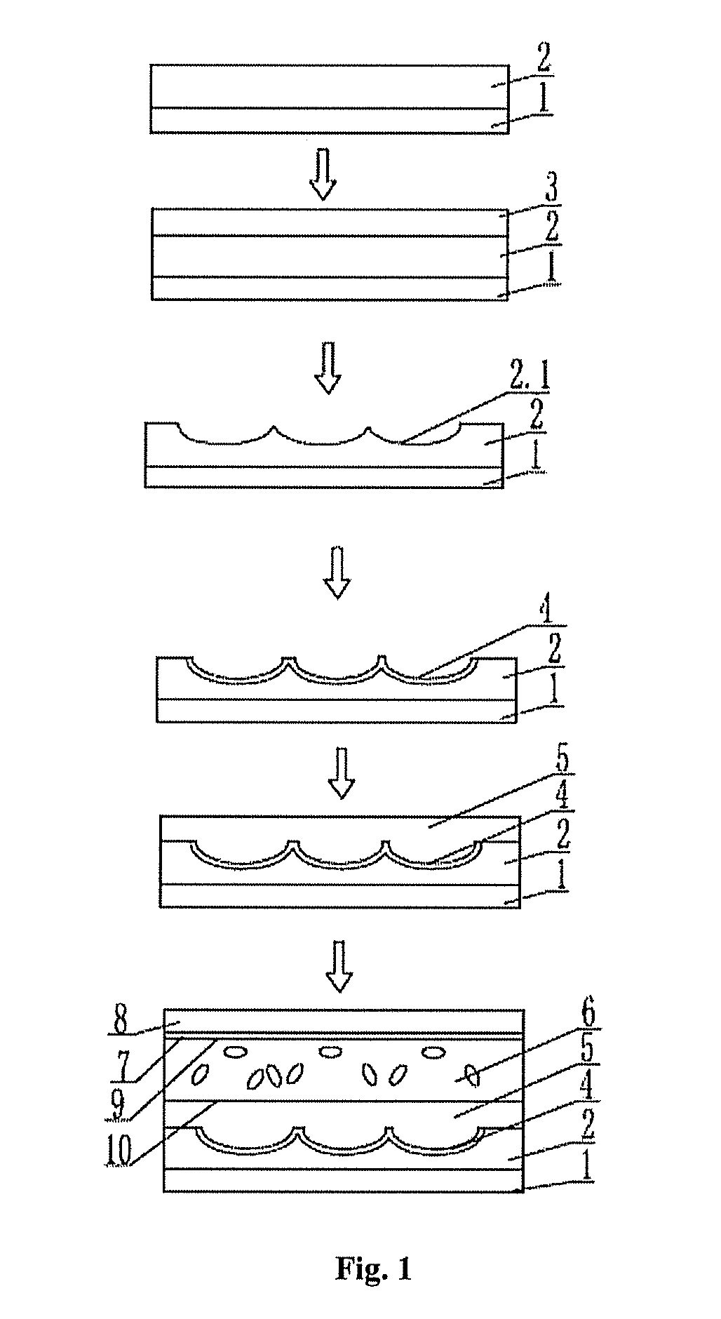
[0022]FIG. 1 is a flowchart of a method for producing a 2D / 3D switchable integral imaging liquid crystal cell according to the present disclosure. The method includes the following steps: 1) coating a UV adhesive layer 2 on a lower substrate 1; 2) imprinting grooves 2.1 on the UV adhesive layer 2 by using an array and then UV-curing the UV adhesive layer 2 with the grooves 2.1 thereon; 3) coating a lower ITO (indium tin oxide) film 4 on the cured UV adhesive layer 2, and planarizing the grooves 2.1 by using silicon nitride; and 4) coating a liquid crystal cell sealant, filling liquid crystals, and then forming a liquid crystal cell by the lower substrate 1 and an upper substrate 8 which is coated with an upper ITO film 7 on a lower surface thereof.

example 2

[0023]The method of producing a 2D / 3D switchable integral imaging liquid crystal cell according to the present disclosure includes the following steps: 1) coating a UV adhesive layer 2 on a lower substrate 1; 2) imprinting grooves 2.1 on the UV adhesive layer 2 and then UV-curing the UV adhesive layer 2 with the grooves 2.1 thereon; 3) coating a lower ITO (indium tin oxide) film 4 on the cured UV adhesive layer 2, and planarizing the grooves 2.1 by using silicon nitride; and 4) coating a liquid crystal cell sealant, providing a channel and a reserved space for the liquid crystals, and filling the reserved space and the channel with the liquid crystals through suction after a liquid crystal cell is formed by the lower substrate 1 and an upper substrate 8 which is coated with an upper ITO film 7 on a lower surface thereof.

[0024]The UV adhesive can be shadowless adhesive in the examples described above. The non-groove region can be also covered with silicon nitride when the grooves 2.1...


PUM

PropertyMeasurementUnit
transparent conductiveaaaaaaaaaa
transparentaaaaaaaaaa
voltageaaaaaaaaaa

Abstract

The present disclosure discloses a method for producing a 2D / 3D switchable integral imaging liquid crystal cell, and a liquid crystal cell, the method comprising the following steps: 1) coating a UV adhesive layer on a lower substrate; 2) imprinting grooves on the UV adhesive layer by using an array and then UV-curing the UV adhesive layer; 3) coating a lower transparent conductive film on the cured UV adhesive layer, and planarizing the grooves; and 4) forming a liquid crystal cell with the lower substrate and an upper substrate which is coated with an upper transparent conductive film on a lower surface thereof. 2D and 3D displays are switchable in the liquid crystal cell obtained by the method of the present disclosure, thereby achieving comparable displays of 2D and 3D images through simple and convenient operations.

Description

FIELD OF THE INVENTION[0001]The present disclosure relates to a method for producing an integral imaging liquid crystal cell, in particular to a method for producing a 2D / 3D switchable integral imaging liquid crystal cell, and a liquid crystal cell.BACKGROUND OF THE INVENTION[0002]Generally, liquid crystal cells in the prior art are incompatible with 2D and 3D displays. Grating arrays for integral imaging are normally physically-structured convex lens arrays. Liquid crystal cells for 3D images will generate blurred images with degraded resolution when used for displaying 2D images. Moreover, methods for producing liquid crystal cells are generally complex and inconvenient to operate.SUMMARY OF THE INVENTION[0003]A technical problem to be solved by the present disclosure is to provide a method for producing a 2D / 3D switchable integral imaging liquid crystal device, which allows switching between the display of a 2D image and display of a 3D image to realize display compatibility of 2...

Claims


Application Information

Patent Timeline
Patent Type & Authority Applications(United States)
IPC IPC(8): G02F1/1333G02F1/137G02B27/22G02B30/10G02B30/25
CPCG02F1/1333G02F2001/133357G02F1/137G02B27/22G02F1/29Y10T156/1039G02B30/25G02F1/133357G02F1/294G02B30/10G02B30/27
Inventor LIAO, QIAOSHENGYANG, CHIH-MING
Owner TCL CHINA STAR OPTOELECTRONICS TECH CO LTD
Why Eureka
Try Eureka