Light source system and related projection system

a technology of light source and projection system, which is applied in the field of light source system and related projection system, can solve the problems of affecting the light emitting efficiency and life the working life and light emission efficiency of the light source device are limited, and the wavelength conversion efficiency of red phosphor tends to be relatively low, so as to increase the efficiency of the light source system and reduce the effect of wavelength conversion efficiency and low wavelength conversion efficiency

Active Publication Date: 2015-09-10
APPOTRONICS CORP LTD
View PDF45 Cites 23 Cited by
  • Summary
  • Abstract
  • Description
  • Claims
  • Application Information

AI Technical Summary

Benefits of technology

[0014]It divides the first light into the light in the first wavelength range and the light in the second wavelength range, and these two lights and the at least part of the second light are outputted sequentially; thus, in certain time intervals only two lights are output, and in certain other time intervals only one light is output, so that two spatial light modulators can be used to modulate the three lights. Further, the light source system can use a wavelength conversion material having a relatively high wavelength conversion efficiency to generate a converted light and then divide that converted light into two other colors, where the two other color lights would otherwise have required two wavelength conversion material having relatively low wavelength conversion efficiency; this increases the efficiency of the light source system.

Problems solved by technology

However, in such a light source device that uses phosphors, red phosphor is a bottleneck that limits that working life and light emission efficiency of the light source device.
The wavelength conversion efficiency of red phosphor tends to be relatively low; the energy not converted to red light becomes heat, which quickly raises the temperature of the phosphor, which in turn adversely affects its light emitting efficiency and life, causing a vicious cycle.

Method used


Image

  • Light source system and related projection system
  • Light source system and related projection system
  • Light source system and related projection system

Examples


first embodiment

[0054

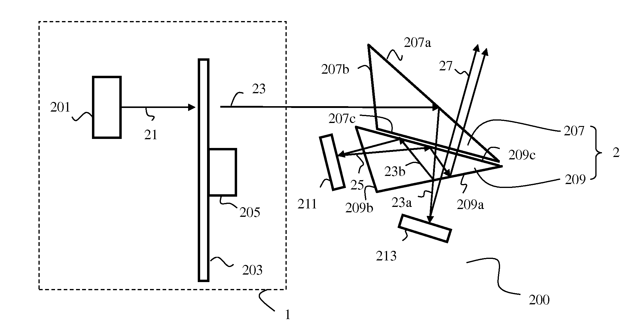
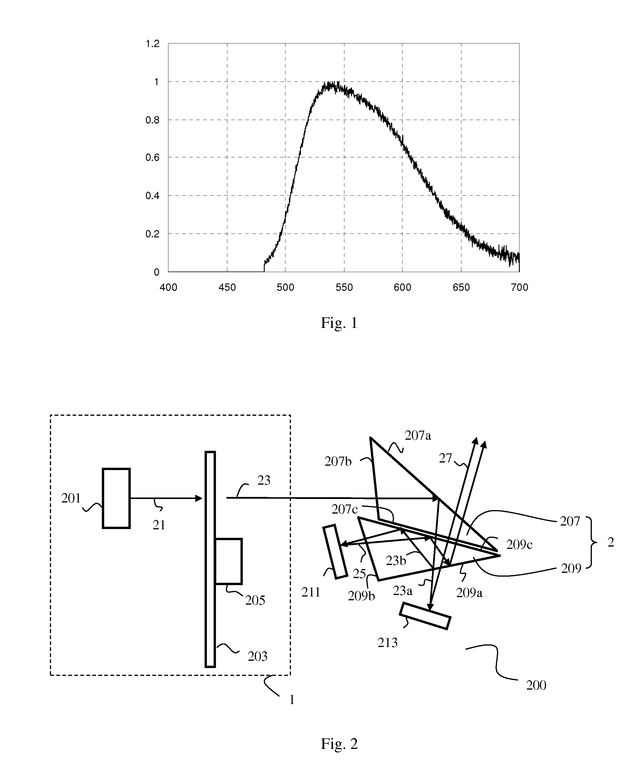
[0055]Referring to FIG. 2, which schematically illustrates a light source system according to an embodiment of the present invention. The light source system of this embodiment includes a light generating device 1, a light division system 2, a first spatial light modulator 211, and a second spatial light modulator 213.

[0056]The light generating device 1 includes an excitation light source 201 for generating an excitation light, a wavelength conversion layer 203, and a first drive device 205. The wavelength conversion layer 203 includes a first segment and a second segment. The first segment is provided with a first wavelength conversion material that absorbs the excitation light and emits a first light; the second segment is a light transmitting segment, which transmits the excitation light as a second light. In this embodiment, the excitation light source 201 generates a blue excitation light. The excitation light source 201 is preferably a laser source, but can also be an LED...

second embodiment

[0070

[0071]Refer to FIG. 5, which schematically illustrates a light source system according to another embodiment of the present invention. In this embodiment, the light source system 500 includes a light generating device 1, a light division system 2, a first spatial light modulator 511 and a second spatial light modulator 513. The light generating device 1 includes an excitation light source 501, a wavelength conversion layer 503 and a first drive device 505.

[0072]Differences between this embodiment and the embodiment of FIG. 2 include:

[0073]The light division system 2 includes a filter plate 509 and a reflector 507. The filter plate 509 receives the yellow light 53 and blue light 55 sequentially outputted by the wavelength conversion layer 503; it transmits the blue light 55 and the green component 53a of the yellow light 53 and outputs them to the DMD 511 via a first light path, and reflects the red component 53b of the yellow light 53 to the reflector 507. The reflector 507 ref...

third embodiment

[0075

[0076]Refer to FIG. 6, which schematically illustrates a light source system according to another embodiment of the present invention. In this embodiment, the light source system 600 includes a light generating device 1, a light division system 2, a first spatial light modulator 611 and a second spatial light modulator 613. The light generating device 1 includes an excitation light source 601, a wavelength conversion layer 603 and a first drive device 605.

[0077]Differences between this embodiment and the embodiment of FIG. 5 include:

[0078]The light division system 2 includes a first light division device 609, a second drive decide 607, and a first control device (not shown in the drawing). To increase the utilization efficiency of the output light of the light generating device 1, the light source system 600 additionally includes a light collecting lens 615 disposed on the light path between the light generating device 1 and the light division system 2, for collecting the light...


PUM


Abstract

A light source system (200), comprises: a light-emitting device (1) for emitting a first light and a second light in sequence; a beam splitting system (2) with which the first light emitted from the light-emitting device (1) is divided into one beam in a first range of wavelength and the other beam in a second range of wavelength, respectively emitted along a first optical path and a second optical path, and also with which at least a part of the second light emitted from the light-emitting device (1) is emitted along the first optical path; a first spatial light modulator (211) for modulating the beam emitted from the beam splitting system (2) along the first optical path; a second spatial light modulator (213) for modulating the beam emitted from the beam splitting system (2) along the second optical path. The light source system (200) has the advantages of high light-emitting efficiency and low cost. A projection system comprising the aforementioned light source system (200) is also provided.

Description

BACKGROUND OF THE INVENTION[0001]1. Field of the Invention[0002]This invention relates to lighting and display technologies, and in particular, it relates to a light source system and related projection system.[0003]2. Description of the Related Art[0004]In conventional single-plate digital micromirror device (DMD) system, multiple primary lights sequentially and alternatingly enters the DMD to be modulated. The modulated single-color images rapidly switch on the screen, so that a color image is perceived by the viewer due to mixing of the sequential single-color images by the effect of persistence of vision of the human eyes. In conventional technologies, typically red (R), green (G) and blue (B) primary color lights are used for modulation. A commonly used method of generating a three primary color light sequence is to use an excitation light to excite different segments of a color wheel sequentially to generate different color lights sequentially. In such a structure, the excitat...

Claims


Application Information

Patent Timeline
Patent Type & Authority Applications(United States)
IPC IPC(8): G03B21/20H04N9/31G02B27/14F21V14/08F21V9/40
CPCG03B21/204G03B21/206F21V14/08G02B27/141H04N9/312H04N9/3158H04N9/3105G03B21/005G03B21/20G03B33/08H04N9/3114G03B21/2013G03B21/2033G03B21/2066H04N9/3117H04N9/3164
Inventor HU, FEILI, YICAO, LIANGLIANGYANG, YI
Owner APPOTRONICS CORP LTD
Why Eureka
Try Eureka