Variable-cycle permanent-magnet undulator

a permanent magnet and undulator technology, applied in the direction of permanent magnets, magnetic bodies, magnetic materials, etc., can solve the problems of structurally difficult to adjust the gap between the magnets, the gap space of the undulator may easily change in size, and the structure in which the magnetic field is adjusted in strength to adjust the wavelength of the radiation, etc., to achieve the effect of more stably adjusting the radiation wavelength, adjusting the period of the magnetic field, and sufficient strong magnetic field

Active Publication Date: 2015-09-10
KOREA ATOMIC ENERGY RES INST
View PDF11 Cites 8 Cited by
  • Summary
  • Abstract
  • Description
  • Claims
  • Application Information

AI Technical Summary

Benefits of technology

[0032]According to the present invention, the undulator may be adjusted in period, but not in strength of the magnetic field, to more stably adjust the wavelength of the radiation. According to the undulator on the related art, the magnetic field may change in strength to adjust the wavelength of the radiation. Thus, when the magnetic field strength changes, the radiation may change in output power. However, according to the present invention, since the magnetic field varies in period and the output power of the radiation may not be affected by the variation of the undulator period, the radiation may be adjusted in wavelength by the desired degree while maintaining the output power of the radiation.
[0033]Also, according to the present invention, since the magnetic field is generated by using the permanent magnets, the sufficient strong magnetic field may be generated without the power consumption.
[0034]Furthermore, the variable-period structure developed according to the related art may be applied to only the planar undulator, but not be applied to the helical undulator. However, according to the present invention, this variable-period structure may be applied to the helical undulator to very easily adjust the period of the magnetic field. Also, this simplified structure in which the magnetic field period varies may significantly reduce a volume of the device in itself. In addition, due to the simplified variable-period structure, the period may be easily and precisely adjusted to precisely adjust the wavelength by the desired degree.

Problems solved by technology

However, the structure in which the magnetic field is adjusted in strength to adjust the wavelength of the radiation may have following several problems.
In case of the planar undulator, even though the permanent magnet is used, the gap space of the undulator may easily change in size.
However, in case of the helical undulator, unlike the planar undulator, it may be structurally difficult to adjust the gap between the magnets (see (B) in FIG. 1).
However, since the magnetic field of the electromagnet is a relatively weak when compared to that of the permanent magnet (thus, since large current has to be applied to form a strong magnetic field that is similar to that of the permanent magnet, it is impossible to form the strong magnetic field at room temperature by using a wire having a small diameter), the radiation may not be effectively generated as well known.
Thus, it may be difficult to obtain the radiation having a desired high output power with a compact size because of the small-sized wire.
However, in case of the prior art 1, since it is very difficult to realize fine movement due to the structural characteristics thereof, it may be very difficult to precisely adjust the distance between the magnets.
Thus, it may be difficult to finely adjust the wavelength of the radiation.
This structure may not be applied to the helical undulator as it is and also be very difficult in design change to be applied to the helical undulator.
However, it may also be impossible to apply the structure of the prior art 2 to the helical undulator.
That is, since the attractive force is applied between the separated permanent magnets even though the repulsive force is applied between the separated ferromagnetic materials, it may be impossible to effectively spread the distance between the magnets.

Method used


Image

  • Variable-cycle permanent-magnet undulator
  • Variable-cycle permanent-magnet undulator
  • Variable-cycle permanent-magnet undulator

Examples


Embodiment Construction

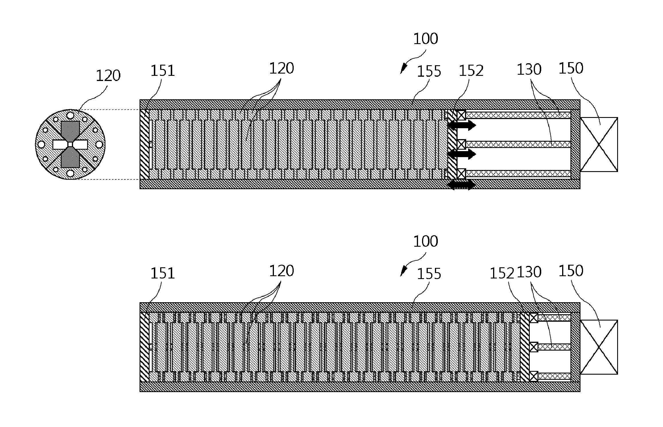
[0051]Hereinafter, a variable-period permanent-magnet undulator including the above-described constitutions according to the present invention will be described in detail with reference to the accompanying drawings.

[0052]The variable-period undulator according to the present invention fundamentally generates magnetic fields by using a permanent magnet. Thus, the variable-period undulator according to the present invention may generate magnetic fields that are very stable and strong without power consumption when compared to an undulator that generates magnetic fields by using an electromagnet. Also, the variable-period undulator according to the present invention may vary in period of a magnetic field to adjust a wavelength of radiation as well known in its name. Thus, the variable-period undulator according to the present invention may realize the output power of the stable radiation without changing in output power of the radiation and also freely adjust the wavelength of the radi...


PUM

PropertyMeasurementUnit
angleaaaaaaaaaa
magnetic fluxaaaaaaaaaa
magnetic fieldsaaaaaaaaaa

Abstract

A variable-period permanent-magnet undulator which is applicable not only to a planar undulator but also to a helical undulator, in which permanent-magnets and ferromagnetic substances are alternately arranged, and the ferromagnetic substance interposed between the permanent-magnets is saturated to thus enable the magnets to be effectively spaced apart from each other by the repulsive force between the permanent-magnets, thereby adjusting the period of the magnetic field in an easy and precise manner.

Description

TECHNICAL FIELD[0001]The present invention relates to a variable-period permanent-magnet undulator.[0002]An undulator is a periodic magnetic or electric structure, i.e., a device for generating light from electron beams in a free electron laser or synchrotron accelerator. When kinetic energy of an electron beam has a relative speed that is close to the speed of light, the magnetic undulator is used. More particularly, the undulator is formed to have a magnetic field that periodically changes in a progress direction of electrons to radiate light having a specific wavelength. Here, a permanent magnet or electromagnet may be periodically disposed to realize the magnetic field. FIG. 1 is a schematic view of a configuration of a general undulator. (A) in FIG. 1 is a view of a planar undulator in which a magnetic field changes in direction within a plan, and (B) in FIG. 1 is a view of a helical undulator in which a magnetic field changes in a helical direction (in (A) of FIG. 1, a distanc...

Claims


Application Information

Patent Timeline
Patent Type & Authority Applications(United States)
IPC IPC(8): H01F7/02H01F1/053
CPCH01F1/053H01F7/0221H05H7/04H05H13/04
Inventor JEONG, YOUNG UKLEE, KI TAEPARK, SEONG HEESHIN, SHANG INJANG, KYUHAMOON, JEONG HOVINOKUROV, NIKOLAY
Owner KOREA ATOMIC ENERGY RES INST
Why Eureka
Try Eureka