Dry air-water heat exchanger

a heat exchanger and dry air technology, applied in air humidification systems, lighting and heating apparatuses, heating types, etc., can solve problems such as continuous growth of bacteria, reduce the temperature of the entering air, reduce the growth of bacteria and scale formation, and improve the cooling efficiency of circulating refrigerant.

Inactive Publication Date: 2015-09-17
HER JIU TECH
View PDF8 Cites 10 Cited by
  • Summary
  • Abstract
  • Description
  • Claims
  • Application Information

AI Technical Summary

Benefits of technology

[0005]In view of the drawbacks in the prior art, the inventor finally completed the dry air-water heat exchanger, namely, the object of the present invention is to provide a dry air-water heat exchanger that may reduce bacterial growth and scale formation, to thereby improve cooling efficiency of circulating refrigerant (or circulating water).
[0006]To achieve the above object according to the invention, a cooling fan, a main tube row, at least an air pre-cooling water tube row, a water evaporator and a catchment chamber are set in a housing, wherein the air pre-cooling water tube row is provided to pre-cool for the entering air, and the water evaporator is provided to evaporate water for heat exchanging after air pre-cooling to thereby lower the temperature of the entering air, and the circulating refrigerant inside the main the row is heat exchanged by the main tube row, to thereby, to thereby cool and lower the temperature of the circulating refrigerant (or circulating water), to improve the cooling efficiency of the circulating refrigerant (or circulating water), and achieve the purpose of reducing bacterial growth and scale formation.

Problems solved by technology

Because there is lack of adequate isolation facilities, biochemical source and bacterial may easily attach inside the cooling tower 12, it causes that bacteria grow continuously.

Method used


Image

  • Dry air-water heat exchanger
  • Dry air-water heat exchanger
  • Dry air-water heat exchanger

Examples


first embodiment

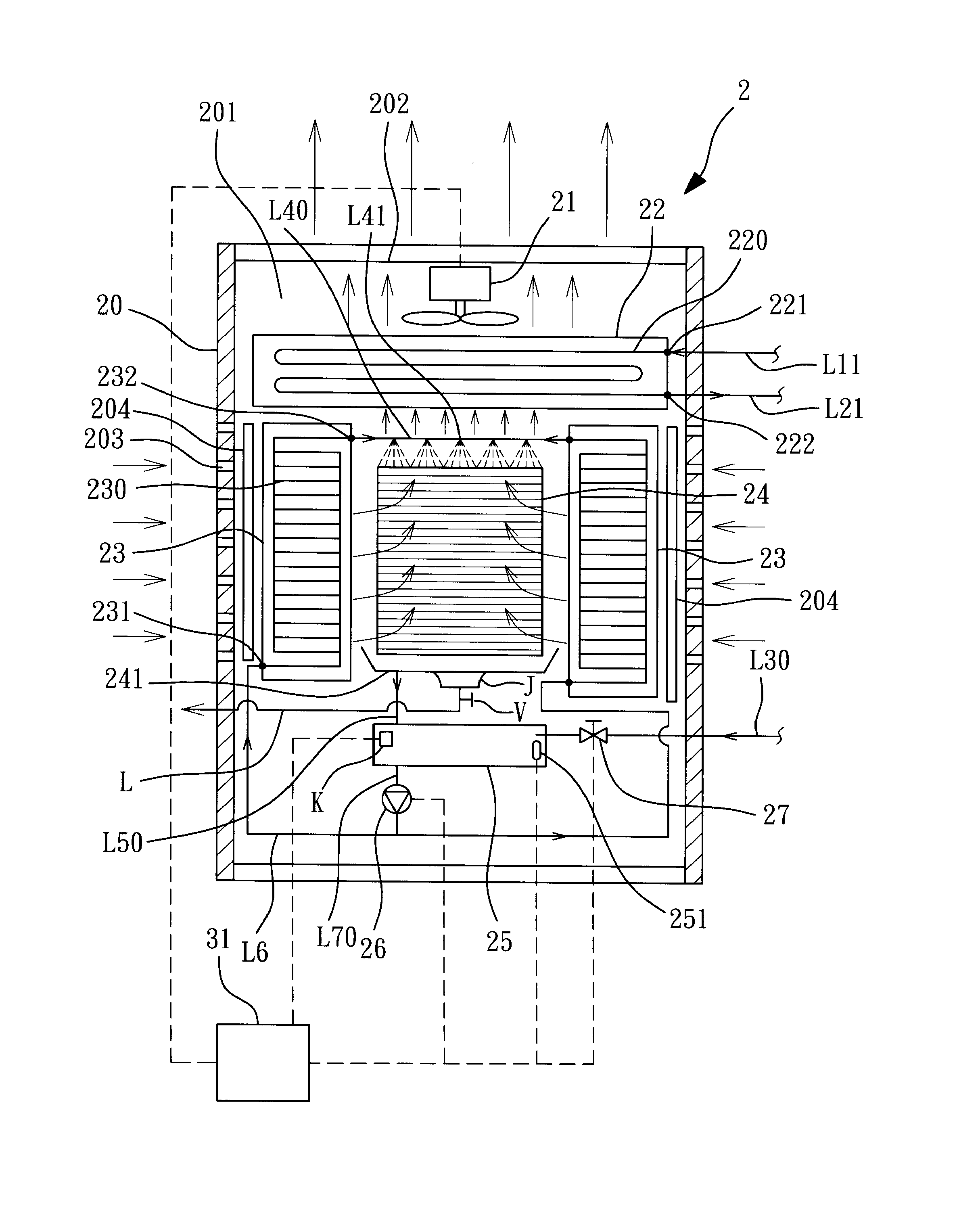
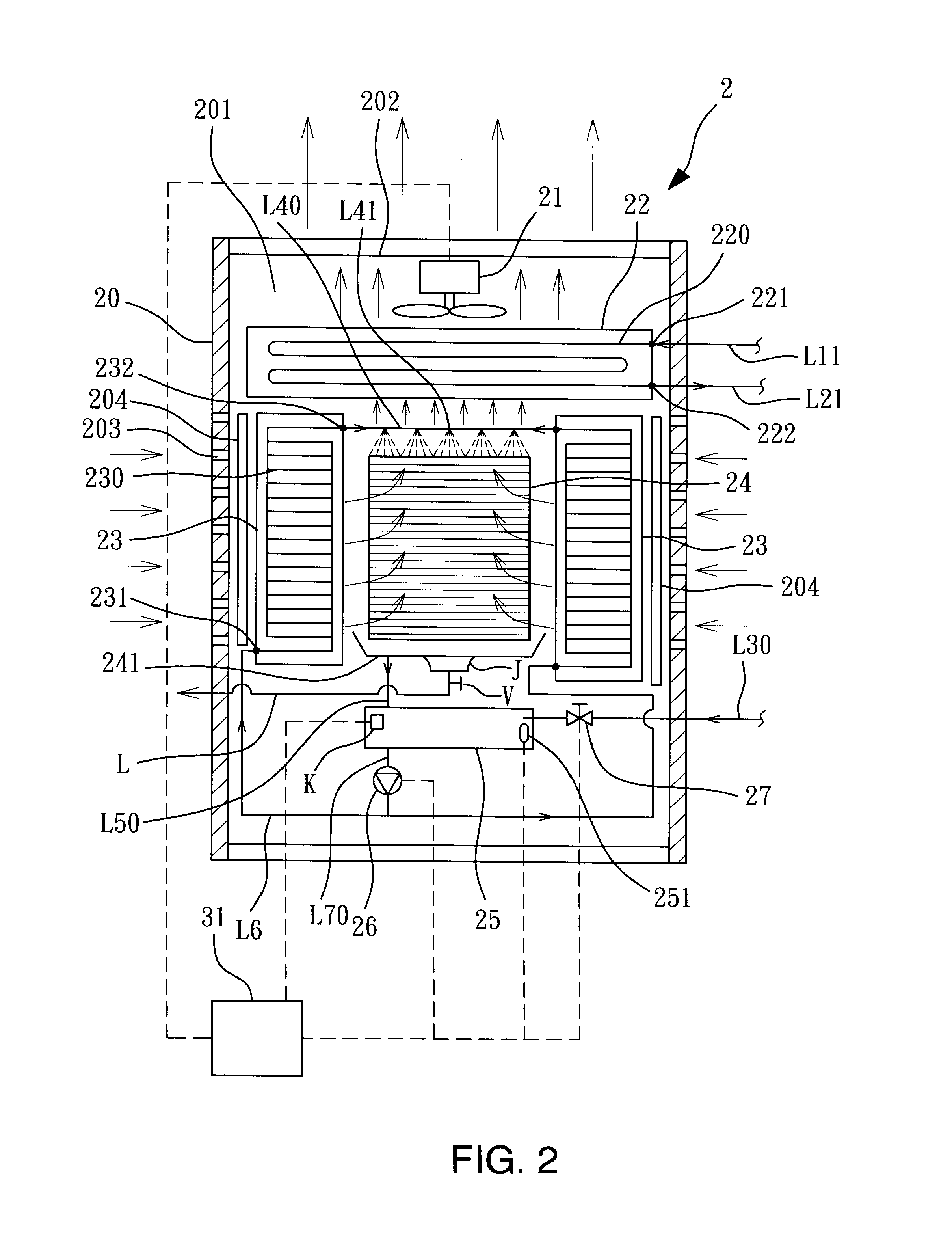
[0013]Please refer to FIG. 2, the present invention is shown, in the dry air-water heat exchanger 2, a cooling fan 21, a main tube row 22, at least an air pre-cooling water tube row 23, a water evaporator 24 and a catchment chamber 25 are set in a housing 20.

[0014]The housing 20, which is a hollow cylinder with an inner capacity 201, an air outlet 202 is set on its top, and at least an air inlet 203 is set on the peripheral edge of the housing 20, the air inlet 203 is close to a filter 204.

[0015]The cooling fan 21 is set on the air outlet 202 of the housing 20 and is controlled by a controller 31.

[0016]The main tube row 22, which is set below the cooling fan 21, is consisted of at least a coil 220, a water inlet end 221 of the coil 220 is connected to a water inlet pipe L11, and a water outlet end 222 of the coil 220 is connected to a water outlet pipe L21 (the water inlet pipe L11 and the water outlet pipe L21 are connected to a chiller, this part is prior art, so it is not shown i...

second embodiment

[0024]the present invention is shown as FIG. 3, and it is the embodiment of the present invention combined with a compressor 50 as an air water cooling system, in the dry air-water heat exchanger 4, a cooling fan 41, a main tube row 42, at least an air pre-cooling water tube row 43, a water evaporator 44, a catchment chamber 45 and the compressor 50 are set in a housing 40.

[0025]The housing 40, which is a hollow cylinder with an inner capacity 401, an air outlet 402 is set on its top, and at least an air inlet 403 is set on the peripheral edge of the housing 40, the air inlet 403 is close to a filter 404.

[0026]The cooling fan 41 is set on the air outlet 402 of the housing 40 and is controlled by a controller 33.

[0027]The main tube row 42, which is set below the cooling fan 41, is consisted of at least a coil 420, a water inlet end 421 of the coil 420 is connected to a first refrigerant pipe L13 and a second end 422 of the coil 420 is connected to a second refrigerant pipe L23, the o...

third embodiment

[0034]the present invention is shown as FIG. 4 and FIG. 5, it is the embodiment of the present invention combined with a compressor 70 and a switching valve 71 as a heating and air conditioning equipment, in the dry air-water heat exchanger 6, a cooling fan 61, a main tube row 62, at least an air pre-cooling water tube row 63, a water evaporator 64, a catchment chamber 65, the compressor 70 and the switching valve 71 are set in a housing 60.

[0035]The housing 60, which is a hollow cylinder with an inner capacity 601, an air outlet 602 is set on its top, and at least an air inlet 603 is set on the peripheral edge of the housing 60, the air inlet 603 is close to a filter 604.

[0036]The cooling fan 61 is set on the air outlet 602 of the housing 60 and is controlled by a controller 34.

[0037]The main tube row 62, which is set below the cooling fan 61, is consisted of at least a coil 620, a first end 621 of the coil 620 is connected to a first refrigerant pipe L14 and a second end 622 of th...


PUM


Abstract

A dry air-water heat exchanger, wherein a cooling fan, a main tube row, at least an air pre-cooling water tube row, a water evaporator and a catchment chamber are set in a housing, wherein the air pre-cooling water tube row is provided to pre-cool for the entering air, and the water evaporator is provided to evaporate water for heat exchanging after air pre-cooling to thereby lower the temperature of the entering air, and the circulating refrigerant (or the circulating water) inside the main the row is heat exchanged by the main tube row, to thereby perform the high-efficiency cooling process with minimum energy and water consumption, to thereby cool and lower the temperature of the circulating refrigerant (or circulating water), to improve the cooling efficiency of the circulating refrigerant (or circulating water), and achieve the purpose of reducing bacterial growth and scale formation.

Description

BACKGROUND OF THE INVENTION[0001]a) Field of the Invention[0002]The invention relates to a dry air-water heat exchanger and, more particularly, a dry air-water heat exchanger to reduce bacterial growth and scale formation, to thereby improve cooling efficiency of circulating refrigerant (or circulating water).[0003]b) Description of the Prior Art[0004]A system schematic diagram of a conventional chiller system is shown in FIG. 1, which includes a chiller 10, an air bellow 11 and a cooling tower 12, the chiller 10 is used to produce cold water, the air bellow 11 is used to convert cold water produced by the chiller 10 into air, the cooling tower 12 is used to perform heat exchange between circulating water and air and let the circulating water flow into the chiller 10 after being cooled to thereby execute cooling operation for system use. The structure of the conventional cooling tower 12 is opened that the circulating water is directly contacted to air in the environment for heat ex...

Claims


Application Information

Patent Timeline
Patent Type & Authority Applications(United States)
IPC IPC(8): F28C3/08F24F6/02F24F1/0063F24F1/0071
CPCF24F6/02F28C3/08F28C1/04F28C1/14F28F2025/005F28F27/003F24F1/0007Y02B30/70F24F1/0063F24F1/0071F25B19/04F25B19/00F24F5/0035F28C1/00
Inventor WENG, KUO-LIANGWENG, CHIEN-LUNWENG, LING-HUAWENG, CHING-JU
Owner HER JIU TECH
Why Eureka
Try Eureka