Light Source Driven by Laser

a laser and light source technology, applied in the field of light sources, can solve the problems of affecting the thermal balance of the hot plasma inside the chamber, the single-wall chamber does not provide sufficient insulation for the blockage of the heat transferred, and the drift is more severe, so as to reduce the heat loss of the light source, minimize the waste of laser power, and improve the thermal balance inside the chamber.

Inactive Publication Date: 2015-09-17
WANG WEIFENG
View PDF6 Cites 16 Cited by
  • Summary
  • Abstract
  • Description
  • Claims
  • Application Information

AI Technical Summary

Benefits of technology

[0012]The object of the present invention is to resolve the above issues in existing laser-driven light sources by providing novel apparatuses and methods to greatly improve t

Problems solved by technology

Consequently, thermal convection of air takes place on the outer surface of the chamber wall and substantially affects the thermal balance of the hot plasma inside the chamber.
Besides, the single-wall chamber does not provide sufficient insulation for the blockage of the heat transferred out of the hot plasma.
The resultant disadvantages for the light sources are:a) Slow warm-up of light source;b) More drift of light output;c) More plasma movement;d) More consumption of laser power.
The unabsorbed laser energy is so high that it not only means a lot of waste of laser power, but also can easily damage the surro

Method used


Image

  • Light Source Driven by Laser
  • Light Source Driven by Laser
  • Light Source Driven by Laser

Examples


Embodiment Construction

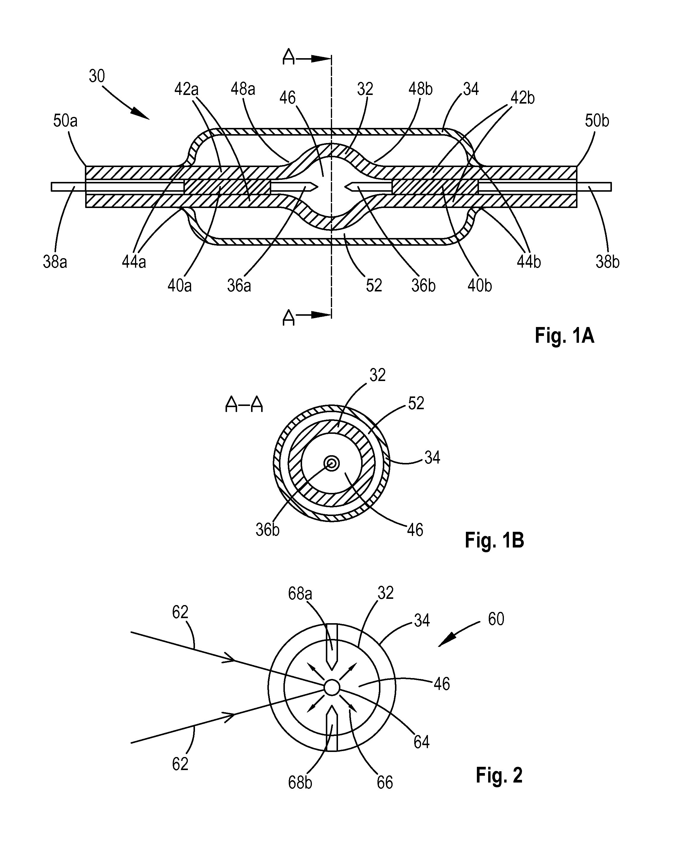
[0028]FIG. 1A shows a typical enveloped chamber assembly 30 comprising a gas-tight single-wall chamber 32 which is covered with an envelop 34. A pair of electrodes 36a and 36b are arranged at the opposite positions inside the chamber and are electrically connected to the two conductors 38a and 38b through members 40a and 40b, which are sealed to the walls 42a and 42b respectively of the two tubes adjoining the chamber. The sealing is made by softening the tubes' walls 42a and 42b in the areas with one or more torches and then pressing the walls or letting the walls collapse by themselves toward the members 40a and 40b. The chamber 32 is entirely jacketed with the envelop 34 with a preferential clearance of at least 0.1 mm, although a fraction of 0.1 mm clearance or even no clearance is also allowed. In this embodiment, the two ends of the envelop 34 are shrunk and attached to the tubes at the locations 44a and 44b where the members 40a and 40b meet the conductors 38a and 38b.

[0029]...


PUM


Abstract

A light source includes an enveloped chamber (32) enclosing an ionizable medium (46) and at least one laser source to provide continuous energy to the plasma (64), i.e. the excited and ionized medium, for producing high-brightness light. The envelop (34) prevents the thermal convection on the inner chamber and provides insulation to the heat transferred out of the plasma so as to generate more stable and stronger emission of light. A method for producing enhanced-brightness light includes the using of multiple chamber assemblies (178a and 178b) and at least one laser source (164) to power the plasma within each chamber assembly in sequence. A method for improving the efficiency of laser usage includes a procedure to re-focus the unabsorbed laser beam (270) back to the same plasma (272) so that more laser energy can be absorbed by the plasma to deliver increased light output.

Description

FIELD OF INVENTION[0001]The present invention relates generally to light sources. More particularly, the invention concerns an apparatus that produces high-brightness light through the excitation of an ionizable medium enclosed in an enveloped chamber, with the excitation energy supplied from one or more external laser sources.BACKGROUND OF THE INVENTION[0002]In regular gas discharge light sources, radiation is produced by hot excited gas, normally in an ionized state, which is sustained by the electric field applied to the discharging gas. The electric field usually is created by two oppositely positioned electrodes set at the operating voltage of the light source. In comparison, light sources, driven or powered by laser, use laser energy instead of electric field as the power source to sustain the ionized gas, i.e. plasma. The absorbed laser energy compensates for the thermal and optical energy loss of the plasma, such that continuous light emission can be produced from the plasma...

Claims


Application Information

Patent Timeline
IPC IPC(8): H01J65/04H05H1/46H05H1/48
CPCH01J65/04H05H1/46H05H1/48H01J61/025H01J61/34H01J61/545H01J37/32
Inventor WANG, WEIFENG
Owner WANG WEIFENG
Why Eureka
Try Eureka