Solar-biomass complementary thermal energy supply system

a technology of complementary thermal energy and biomass, which is applied in the energy industry, machines/engines, refrigeration machines, etc., can solve the problems of large-scale application of solar power energy and low energy utilization efficiency

Inactive Publication Date: 2015-09-24
ZHONGYING CHANGJIANG INTERNATIONAL NEW ENERGY INVESTMENT CO LTD
View PDF3 Cites 13 Cited by
  • Summary
  • Abstract
  • Description
  • Claims
  • Application Information

AI Technical Summary

Benefits of technology

[0022]The solar storage tank of the system of the invention can be filled with multiple media, preferably, the heat storage medium is molten salt, which is much cheaper.

Problems solved by technology

As a result, the energy utilization efficiency is rather low.
However, large-scale application of solar power energy is largely restricted by weather.

Method used


Image

  • Solar-biomass complementary thermal energy supply system
  • Solar-biomass complementary thermal energy supply system
  • Solar-biomass complementary thermal energy supply system

Examples


Embodiment Construction

[0026]For further illustrating the invention, experiments detailing a solar-biomass complementary thermal energy supply system are described below. It should be noted that the following examples are intended to describe and not to limit the invention.

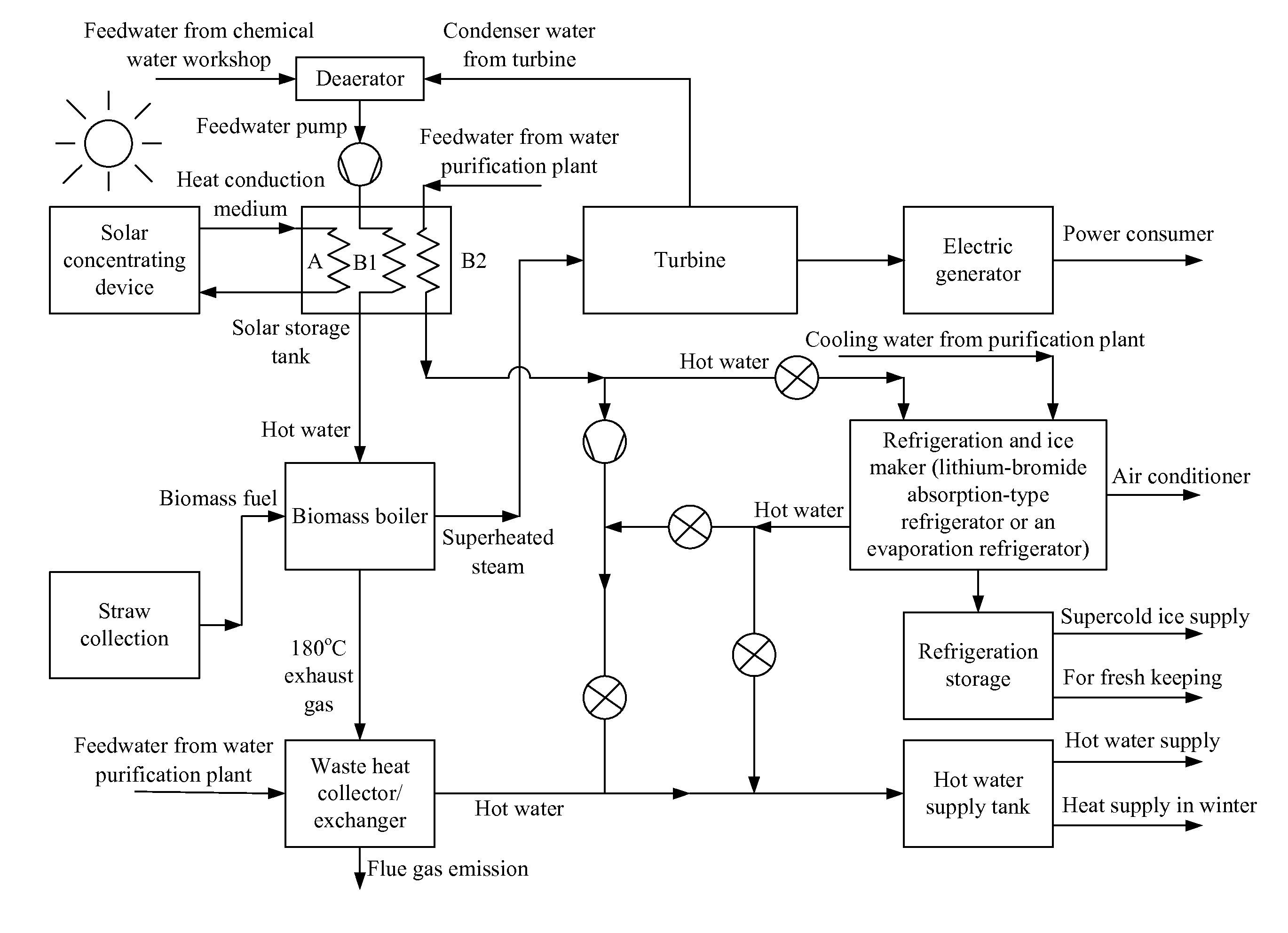
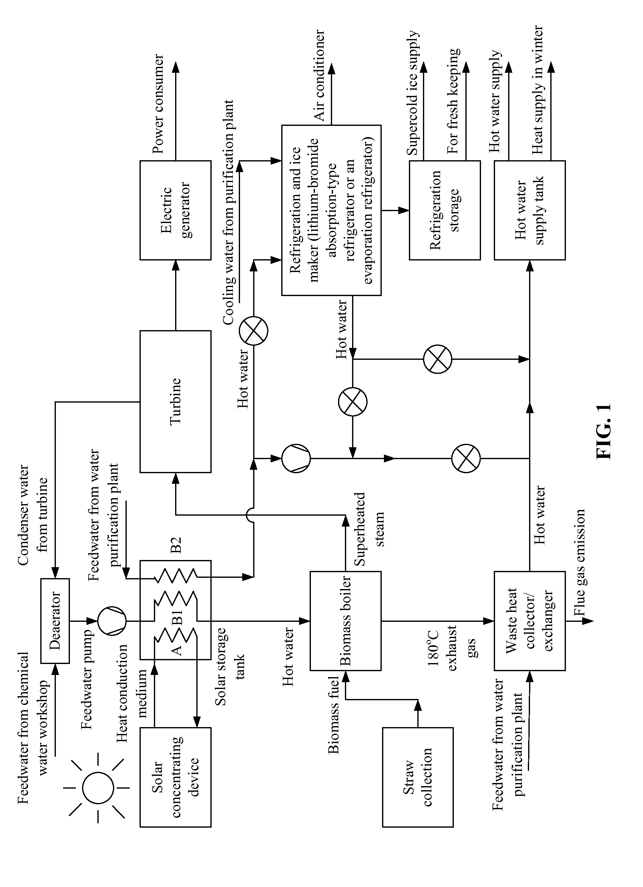
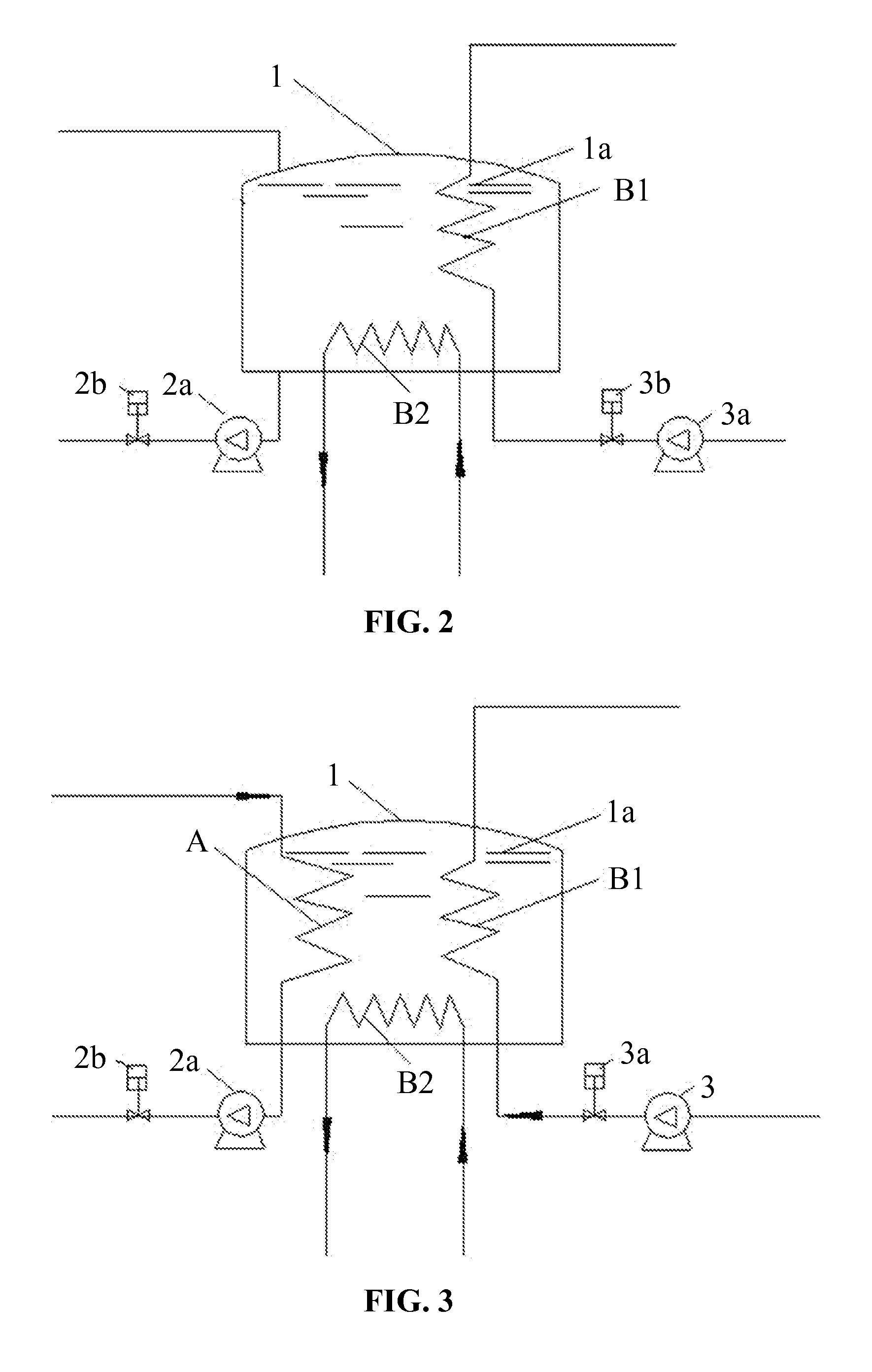
[0027]As shown in FIG. 1, the invention provides a solar-biomass complementary thermal energy supply system, comprising: a solar concentrating device, a solar storage tank comprising a first heat exchanger and a second heat exchanger, a biomass power station comprising a biomass boiler, a central refrigeration and ice maker, and a central hot water supply tank, wherein the solar concentrating device is connected to the solar storage tank via pipes; an inlet of the first heat exchanger B1 of the solar storage tank is connected to an outlet of a feedwater pump of the biomass boiler; an outlet of the first heat exchanger B1 is connected to an inlet of a water feeding system of the biomass boiler; an inlet pipe of the second heat exchanger ...


PUM


Abstract

A thermal energy supply system, including: a solar concentrating device, a solar storage tank including a first heat exchanger and a second heat exchanger, a biomass power station including a biomass boiler, a central refrigeration and ice maker, and a central hot water supply tank. The solar concentrating device is connected to the solar storage tank. The inlet of the first heat exchanger of the solar storage tank is connected to the outlet of a feedwater pump of the biomass boiler. The outlet of the first heat exchanger is connected to the inlet of a water feeding system of the biomass boiler. The inlet pipe of the second heat exchanger of the solar storage tank is connected to the outlet pipe of a water purification plant. The outlet of the second heat exchanger is connected to a thermal energy input pipe of the central refrigeration and ice maker.

Description

CROSS-REFERENCE TO RELATED APPLICATIONS[0001]This application is a continuation-in-part of International Patent Application No. PCT / CN2013 / 088570 with an international filing date of Dec. 5, 2013, designating the United States, now pending, and further claims priority benefits to Chinese Patent Application No. 201210520274.4 filed Dec. 6, 2012. The contents of all of the aforementioned applications, including any intervening amendments thereto, are incorporated herein by reference. Inquiries from the public to applicants or assignees concerning this document or the related applications should be directed to: Matthias Scholl P.C., Attn.: Dr. Matthias Scholl Esq., 245 First Street, 18th Floor, Cambridge, MA 02142.BACKGROUND OF THE INVENTION[0002]1. Field of the Invention[0003]The invention relates to a solar-biomass complementary thermal energy supply system.[0004]2. Description of the Related Art[0005]Conventionally, energy supply systems have been independent from one another. For e...

Claims


Application Information

Patent Timeline
Patent Type & Authority Applications(United States)
IPC IPC(8): F25B27/00F25C1/00F03G6/06F24S23/00F24S90/00
CPCF25B27/002F25C1/00F03G6/06F03G6/067F24D11/003F24D11/005F24D2200/28F25B15/06F25B27/007F28D2020/0078Y02B10/20Y02E10/46Y02E10/50Y02P80/15F02C1/05F03G6/064H02S10/30
Inventor CHEN, YILONGYANG, QINGPINGZHANG, YANFENGLIU, WENYAN
Owner ZHONGYING CHANGJIANG INTERNATIONAL NEW ENERGY INVESTMENT CO LTD
Why Eureka
Try Eureka