Gun sight

a gun sight and holographic technology, applied in the field of holographic image apparatus, can solve the problems of holographic gun sight, existing system drawbacks, complex design, etc., and achieve the effect of improving the batter life of the sight assembly

Active Publication Date: 2015-09-24
ZIEL OPTICS INC
View PDF7 Cites 37 Cited by
  • Summary
  • Abstract
  • Description
  • Claims
  • Application Information

AI Technical Summary

Benefits of technology

[0038]A housing may be provided having a chamber, the H.O.E. and the stable light source are mounted within the sealed chamber. The carrier may be pivotable about an axis of the tie rod. The chamber may be filled with nitrogen. The light source may be horizontally and/or vertically adjustable by means of an adjustment assembly. The adjustment assembly may be a multi-thread pitch adjustment assembly. The H.O.E. may extend at least partially outside of the housing. The housing may include a transparent portion providing for communication between the H.O.E., a mirror and the light source. A mirror may be provided in communication with the H.O.E. and the stable light source. A H.O.E. carrier may be provided to hold the H.O.E. The light source may be a VCSEL. An accelerometer m

Problems solved by technology

Holographic gun sights are well known, but typical designs are complex and may be bulky or have high energy usage.
Adjusting a holographic gun sight for windage and elevation has also presented challenges.
Existing systems have drawbacks.
However, for other applications, such as the holographic gun sight, this shift in wavelength will cause the holographic gun sight to be inaccurate.
As the wavelength of the light shifts, the diffraction angle from a holographic element will change, which will result in movement of the projected holographic image and give an inaccurate reticle position relative to the target.
For either case using a thermoelectric cooler increases the physical size of the laser source asse

Method used


Image

  • Gun sight
  • Gun sight
  • Gun sight

Examples


Embodiment Construction

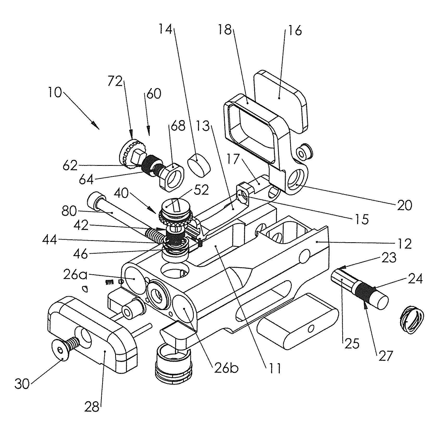
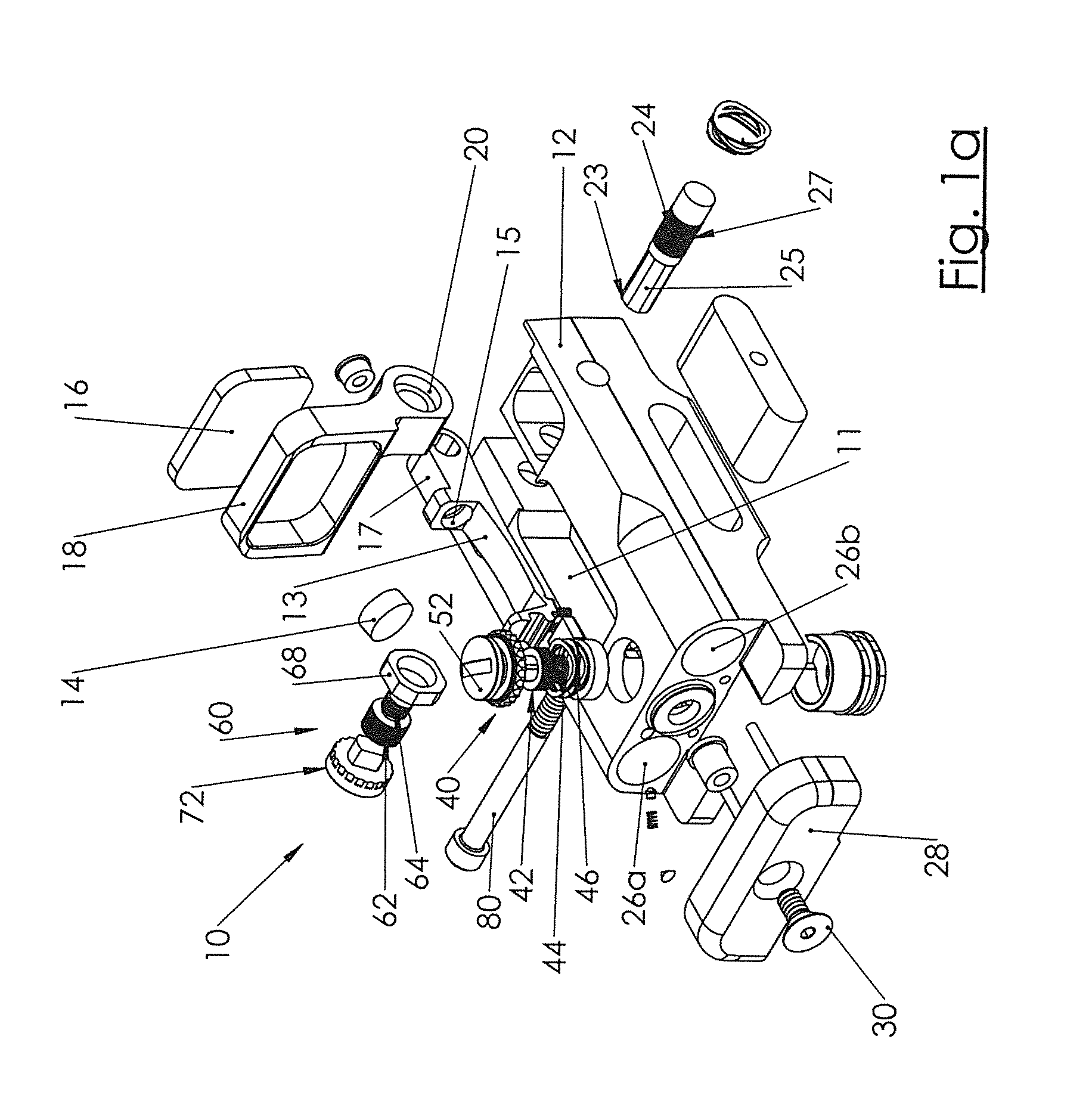
[0071]The present invention relates generally to a sight assembly for a weapon for reconstructing a virtual image used to assist in operation of the weapon. Particular examples will be described, including a variety of features. It should be understood that other examples may include one or more of these features in any combination.

[0072]The illustrated assembly incorporates a wavelength tunable light source (specifically a VCSEL). The assembly allows for slight adjustment of the fixed assembly and a sealed configuration to achieve an improved sight assembly.

Gun Sight Assembly and Adjustment

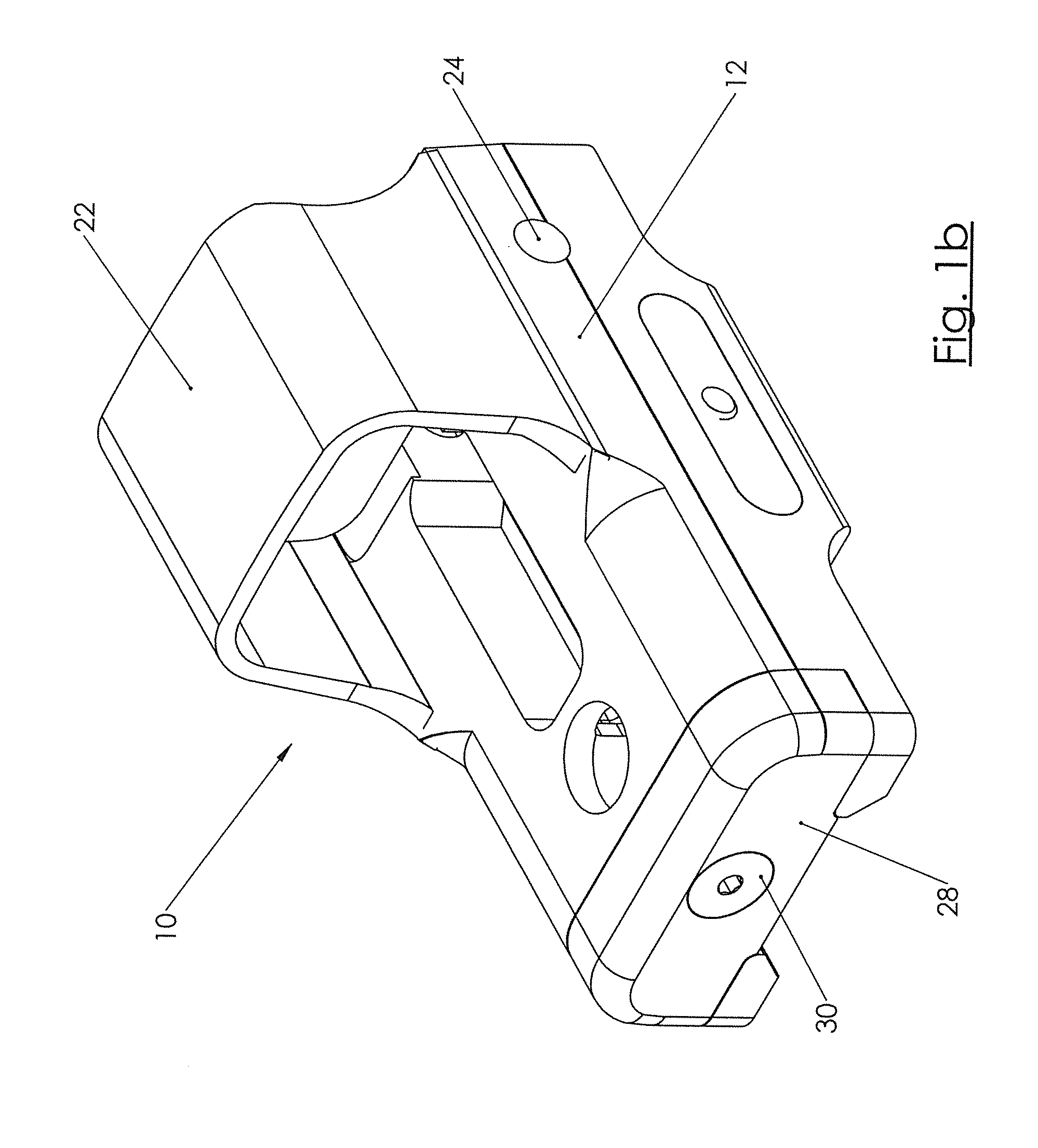
[0073]FIG. 1a illustrates an exemplary holographic gun sight assembly 10 having a housing 12. The housing 12 has an interior chamber 11 defined therein. As shown, the interior chamber 11 extends downwardly from an upper surface of the housing 12. A clear window, not shown, covers the opening in the upper surface. The elements contained within the chamber 11 in the housing are sealed therein to pr...


PUM


Abstract

A sight assembly for mounting to a weapon is provided. A holographic optical element and a light source are provided in a fixed angular configuration with respect to one another, but may be adjusted either together or individually in a horizontal or vertical direction. A mirror or lens may also be provided. An adjustment mechanism is provided where a shaft includes at least two portions wherein the two portions of the shaft of the screw have different pitch directions and/or pitch dimensions allowing for slight adjustment the assembly. The light source is typically a vertical-cavity surface emitting laser (VCSEL). The wavelength of the VCSEL is controlled by controlling the current it is given. The assembly further allows for perceived image distance adjustment using parallax mismatch. Further, a chassis is provided for holding holographic elements.

Description

CROSS-REFERENCE TO RELATED APPLICATIONS[0001]This utility patent application claims priority from U.S. provisional patent application Ser. No. 61 / 879,393, filed Sep. 18, 2013, the entire content of which is incorporated herein in its entirety, U.S. provisional patent application Ser. No. 61 / 846,251, filed Jul. 15, 2013, the entire content of which is incorporated herein in its entirety, U.S. provisional patent application Ser. No. 61 / 883,532, filed Sep. 27, 2013, the entire content of which is incorporated herein in its entirety, and U.S. provisional patent application Ser. No. 62 / 005,262, filed May 30, 2014, the entire content of which is incorporated herein in its entirety.FIELD OF THE INVENTION[0002]The present disclosure relates to a holographic image apparatus for use with a weapon.BACKGROUND OF THE INVENTION[0003]Holographic gun sights are well known, but typical designs are complex and may be bulky or have high energy usage. Adjusting a holographic gun sight for windage and e...

Claims


Application Information

Patent Timeline
IPC IPC(8): F41G1/34G03H1/22
CPCG03H1/22F41G1/345G03H1/0005G03H1/2249G03H2001/2247G03H2001/2284G03H2227/03G03H2227/06G03H2001/2252G02B23/10G02B27/0189G03H2001/0434G03H2001/0212G03H2001/2255G03H2001/2289G03H2001/261F41G1/30G02B5/32G02B23/2446G02B23/2461G02B23/2476H01S5/06804H01S5/183
Inventor COLLIN, FREDMILLS, KURT DOUGLASDILWORTH, DAVID S.COLLIN, RODSHUBECK, STEPHEN MICHAELHYDE, CHRISTOPHER STEPHEN
Owner ZIEL OPTICS INC
Why Eureka
Try Eureka