Autonomous-travel cleaning robot

a cleaning robot and autonomous technology, applied in carpet cleaners, distance measurement, instruments, etc., can solve the problems of reducing and affecting the cleaning effect of the solar cell array, so as to reduce the time necessary for cleaning work, suppress the cost necessary, and improve work efficiency

Inactive Publication Date: 2015-10-01
MIRAIKIKAI
View PDF11 Cites 32 Cited by
  • Summary
  • Abstract
  • Description
  • Claims
  • Application Information

AI Technical Summary

Benefits of technology

[0021]In the first aspect, the cleaning unit passes through the place where the floating is generated after the floating is eliminated, so that the generation of the portion that is not cleaned due to the floating can be prevented. Additionally, the cleaning unit passes through the place where the floating is generated again only when the floating is generated. That is, because the cleaning is performed again only when the floating is generated, a time necessary for the cleaning work can be shortened compared with the case that the cleaning is always performed again at a place where possibly the floating is generated. Accordingly, the work efficiency can be improved to suppress the cost necessary for the cleaning work.
[0022]In the second aspect, only the inclination of the robot main body is detected, so that the generation of the floating can be detected with the simple configuration.
[0023]In the third aspect, because the floating is detected by detecting a load torque of a motor, it is not necessary to provide a special sensor that detects the floating. Therefore, the configuration of the controller can be simplified.
[0024]In the fourth aspect, the travel on the flat surface is stopped when the inclination angle of the structure is greater than or equal to the predetermined angle, namely, when the angle at which the cleaning cannot be performed is detected, so that the robot can be prevented from dropping from the flat surface.
[0025]In the fifth aspect, the robot is held in the base before the inclination angle of the structure is greater than or equal to the predetermined angle, so that the robot can surely be prevented from dropping from the flat surface even if the inclination angle of the structure increases. When the inclination angle of the structure decreases, the robot moves from the base to the flat surface, so that the cleaning of the flat surface can be started. That is, the cleaning of the flat surface and the return to the base are automatically switched according to the inclination of the structure, so that the flat surface of the structure can automatically be cleaned.
[0026]In the sixth aspect, the robot is fixed to the structure by the absorbing unit before the inclination angle of the structure is greater than or equal to the predetermined angle, so that the robot can surely be prevented from dropping from the flat surface even if the inclination angle of the structure increases. When the inclination angle of the structure decreases, the robot fixed by the fixing unit is released to be able to travel on the flat surface. Thus, the cleaning of the flat surface can be started. That is, the cleaning of the flat surface and the fixing to the structure are automatically switched according to the inclination of the structure, so that the flat surface of the structure can automatically be cleaned.

Problems solved by technology

Therefore, when a light receiving surface of the solar cell array (that is, a solar cell module) or the condensing mirror gets dirty, in the solar power generation, light transmission of a cover glass constituting the light receiving surface of the solar cell module degrades according to a level of dirt to decrease a power generation amount.
That is, in the solar power generation or solar thermal power generation, when the light receiving surface of the solar cell module or condensing mirror gets dirty, power generation performance degrades largely.
On the other hand, because the large-scale solar power generation facility has a huge surface area, it is difficult for a person to clean to remove dirt on the surface of the solar cell array.

Method used


Image

  • Autonomous-travel cleaning robot
  • Autonomous-travel cleaning robot
  • Autonomous-travel cleaning robot

Examples


Embodiment Construction

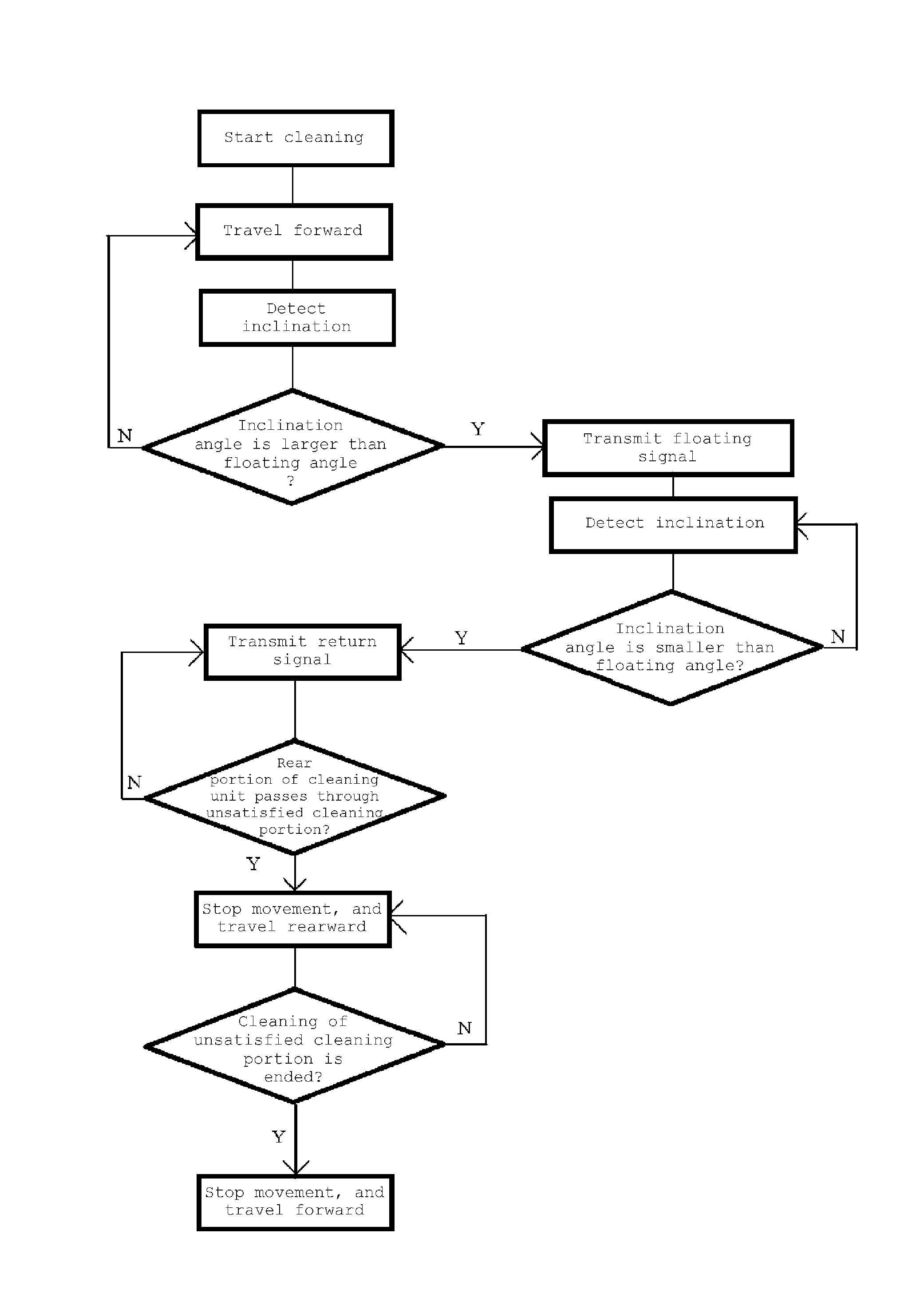
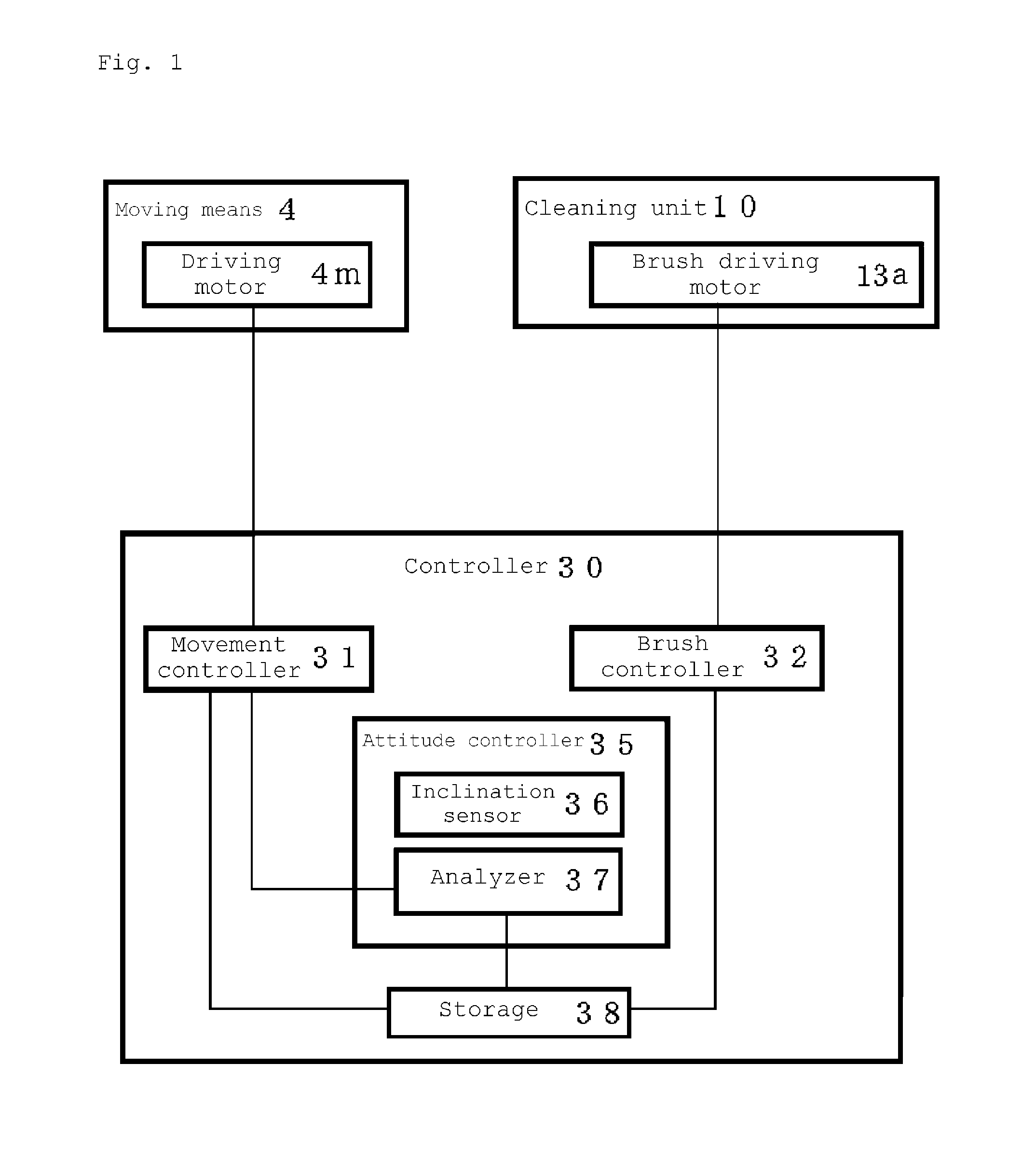
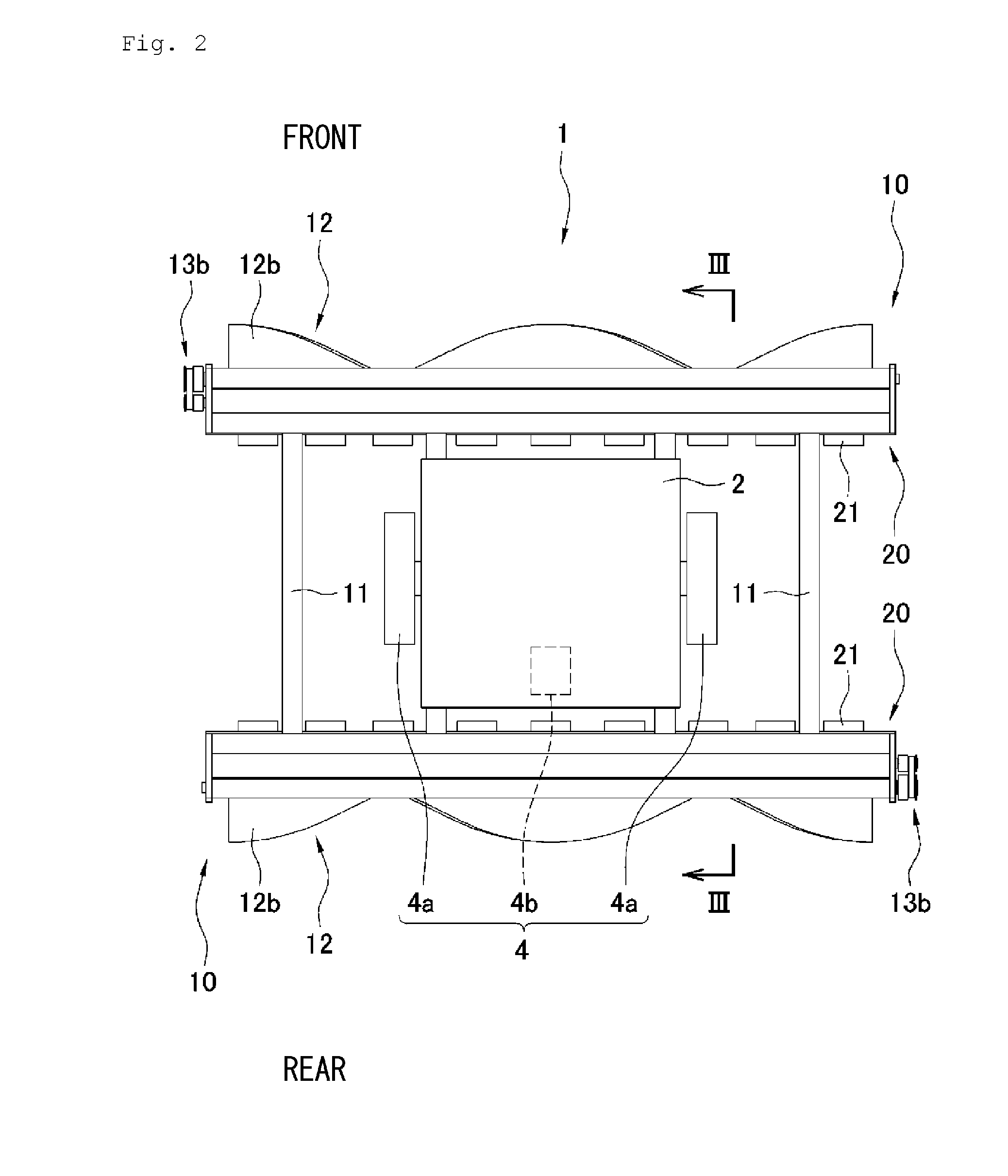
[0107]In some of the solar cell modules of the solar power generation or the condensing mirrors of the solar thermal power generation, the inclination changes in order to maintain power generation efficiency at a high level (see FIG. 10). In the case that the self-propelled cleaning robot 1 cleans the light receiving surface of the solar cell module or condensing mirror in which the inclination changes, the following control can be performed when the controller 30 can understand the inclination angle of the light receiving surface or the change in inclination angle.

[0108]There is no particular limitation to a method in which the controller 30 understands the inclination angle of the light receiving surface of the solar cell module or condensing mirror or the change in inclination angle. For example, a signal regarding the inclination angle of the light receiving surface of the solar cell module or condensing mirror is transmitted to the controller 30 from the outside (such as a cont...


PUM


Abstract

Provided is an self-propelled cleaning robot that can efficiently clean a flat surface even if a step is formed. The self-propelled cleaning robot that self-travels on a structure to clean a flat surface of the structure, the structure being installed in an outdoor location, the robot includes: a robot main body (2) in which a self-propelled moving means(4) is provided; a cleaning unit (10) that is provided in a front portion and/or a rear portion of the robot main body (2); and a controller (30) that controls activation of the moving means (4). At this point, the controller (30) includes an attitude controller (35) that detects an attitude of the robot main body (2), the attitude controller (35) includes a floating detection sensor (36) that detects floating in one of the front portion and the rear portion of the robot main body (2), and, when the floating detection sensor (36) detects the floating in one of the front portion and the rear portion of the robot main body (2), the controller (30) controls the activation of the moving means (4) such that the cleaning unit (10) passes through a place where the floating is detected after the floating is eliminated.

Description

[0001]The present invention relates to a self-propelled cleaning robot. More particularly, the present invention relates to a self-propelled cleaning robot that cleans a surface of a solar cell array used in solar power generation and a surface of a condensing mirror used in solar thermal power generation.BACKGROUND ART[0002]Nowadays, a demand for power generation using renewable energy increases, and particularly solar power generation or solar thermal power generation using sunlight attracts attention.[0003]For example, a solar power generation facility ranges from a facility having a power generation capacity of about 3 kilowatts to about 4 kilowatts provided in a standard home to a commercial large-scale power generation facility having a power generation capacity exceeding 1 megawatt, and is expected as an alternative power generation facility for thermal power generation or nuclear power generation. Even in the solar thermal power generation facility, there are many large-scal...

Claims


Application Information

Patent Timeline
Patent Type & Authority Applications(United States)
IPC IPC(8): A47L11/38A47L9/28H02S40/10
CPCA47L11/38A47L2201/04A47L9/2826H02S40/10Y02E10/40F24S40/20Y02E10/50
Inventor MIYAKE, TOHRUMATSUUCHI, HIDETOMORITA, KAZUO
Owner MIRAIKIKAI
Why Eureka
Try Eureka