Laser welded shaped steel

Inactive Publication Date: 2015-10-01
NISSHIN STEEL CO LTD
View PDF2 Cites 4 Cited by
  • Summary
  • Abstract
  • Description
  • Claims
  • Application Information

AI Technical Summary

Benefits of technology

[0018]As a result, the laser-welded shaped steel provided by the present invention has stable joint strength, and exhibits no drop in welded portion corrosion resistance even when, in particular, the laser-we

Problems solved by technology

In some instances, therefore, the shape conditions of the melted section can vary and the desired joint strength may fail to be achieved, depending on differences in the incidence angle of laser beam with respect to the flange material, the aim position of laser beam with respect to the edge section of the web material, and the energy of

Method used


Image

  • Laser welded shaped steel
  • Laser welded shaped steel
  • Laser welded shaped steel

Examples


Example

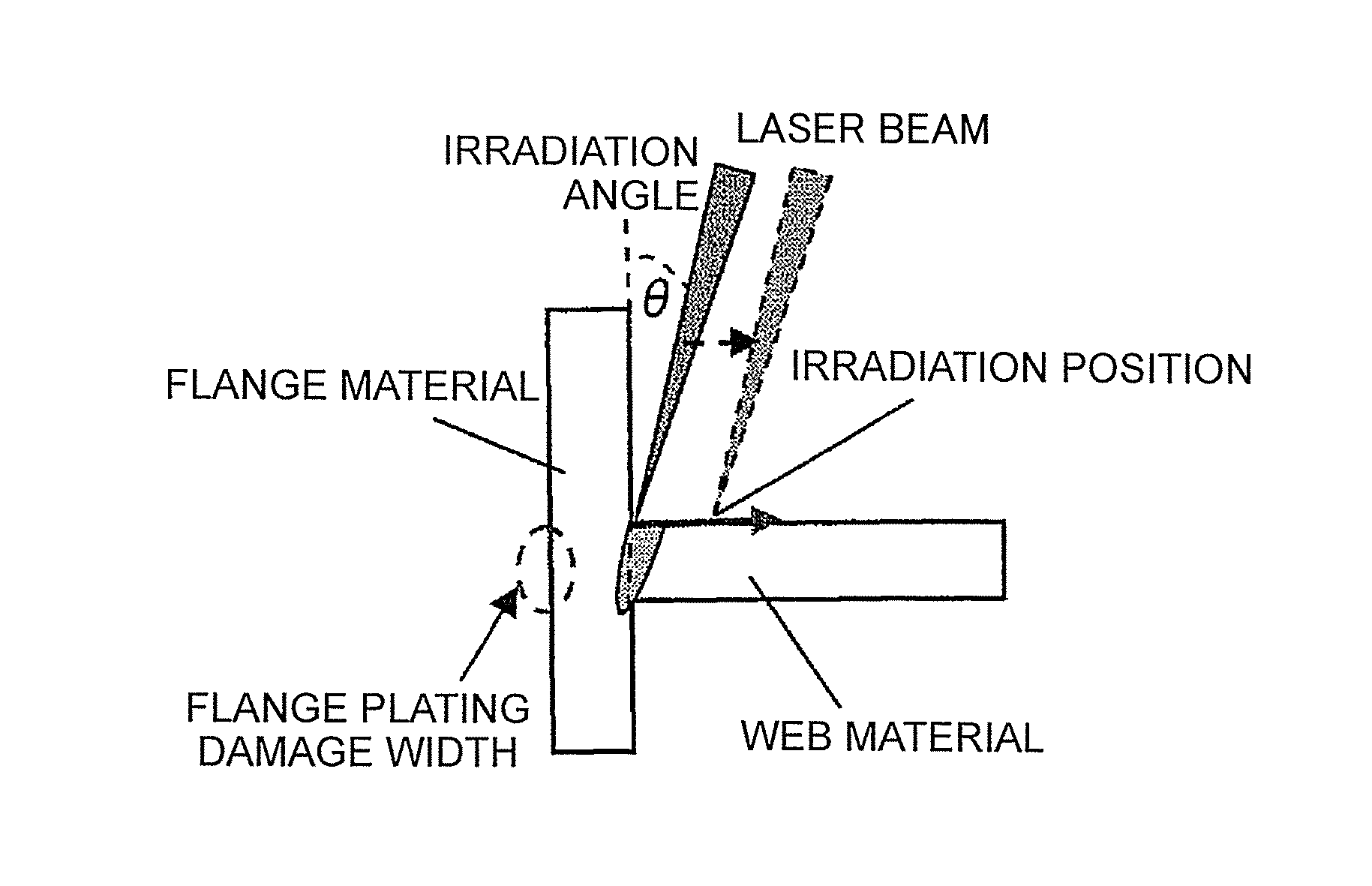
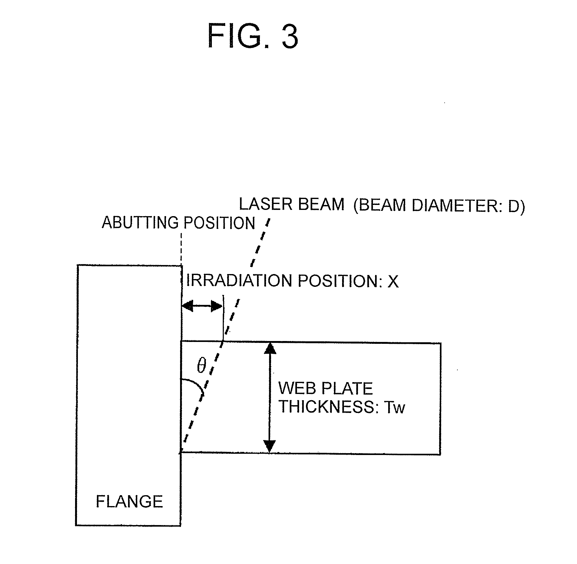
[0022]Upon welding of a T-shaped joint formed by pressing of an edge section of a web material perpendicularly against a flange material on the basis of one-pass laser beam irradiation of the T-shaped joint from one side (front or rear side of the web material), a desired joint strength fails to be obtained unless the irradiation angle θ of laser beam with respect to the flange material and the irradiation position of laser beam with respect to edge section of the web material, illustrated in FIG. 1, are set properly. In a case where a plated steel plate is used as the material, the plating layer of the flange material at the face that abuts the web material may be damaged unless the irradiation angle θ and the irradiation position are set properly.

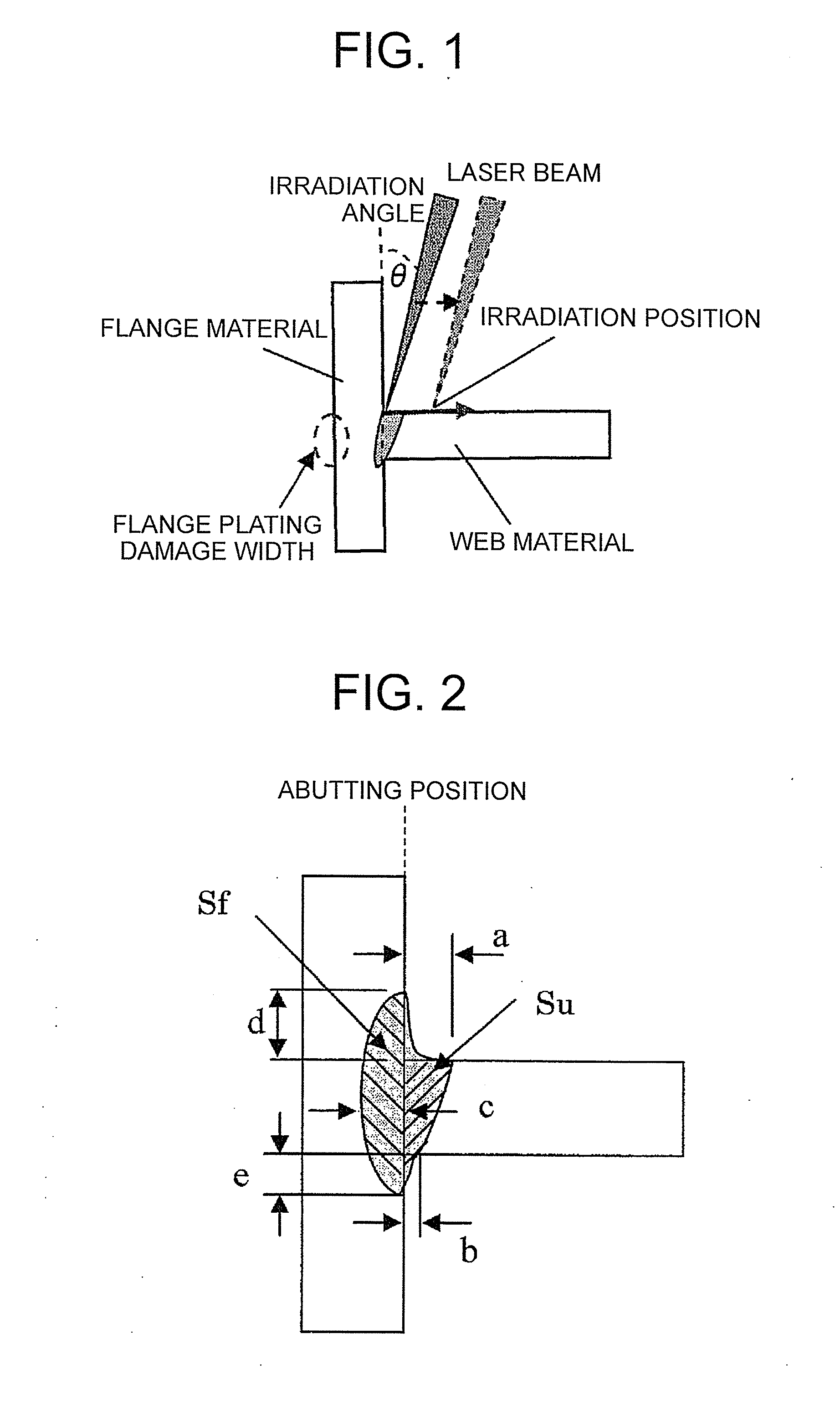
[0023]For instance, when the irradiation angle θ of the laser beam is reduced, there increase the flange front melting width d and the flange rear melting width e at positions above and below the intersection point (abutting position) of ...


PUM

PropertyMeasurementUnit
Surface areaaaaaaaaaaa

Abstract

A welded portion shape of a cross-section perpendicular to the shaped steel longitudinal direction is set to satisfy a>0 mm, b>0 mm, c≧0.14Tw, d≧0 mm, e≧0 mm, a+d≦2 mm and b+e≦2 mm; where a is a front melting width of the web material (on the laser beam irradiation side), b is a rear melting width of the web material (on the laser beam non-irradiation side), c is a maximum weld penetration depth, in a plate pressure direction, into the flange material, d is a front melting width of the flange material (on the laser beam irradiation side), e is a rear melting width of the flange material (on the laser beam non-irradiation side), and Tw is the plate thickness of the web material.

Description

TECHNICAL FIELD[0001]The present invention relates to welded shaped steel, in which a T-shaped welded joint is formed by laser welding, using laser beam as a heat source.BACKGROUND ART[0002]Laser welding methods that involve irradiating laser beam onto a T-shaped joint between a flange material and a web material, have been studied as methods for producing shaped steel such as T-shaped steel or H-shaped steel, which is used for instance in beams that make up building frames of buildings.[0003]As illustrated in Patent literature 1, for instance, two metal plates are butted perpendicularly to each other, and two laser beams are irradiated simultaneously, along the butting section, onto opposing positions, from both the front and rear faces of the butting metal plates.[0004]In such a method, laser beam is irradiated onto the butting section from the directions of both sides of the web material, which is not necessarily efficient in terms of enhancing productivity.[0005]Therefore, the a...

Claims


Application Information

Patent Timeline
IPC IPC(8): B23K26/24B23K26/32
CPCB23K26/3206B23K26/243B23K2103/04B23K26/32B23K2103/50B23K26/242B23K26/21B23K26/322
Inventor SAKURADA, YASUHIRONAKAKO, TAKEFUMIASADA, HIROSHI
Owner NISSHIN STEEL CO LTD
Why Eureka
Try Eureka