System for a thermodynamic cycle, control unit for a system for a thermodynamic cycle, method for operating a system, and arrangement with an internal combustion engine and a system

a control unit and thermodynamic cycle technology, applied in the direction of steam engine plants, climate sustainability, light and heating apparatus, etc., can solve the problem of low limit determined by process control stability, and achieve the effect of simple and cheap configuration, high degree of precision, and increased quantity

Inactive Publication Date: 2015-10-01
MOTOREN & TURBINEN UNION FRIEDRICHSHAFEN GMBH
View PDF4 Cites 12 Cited by
  • Summary
  • Abstract
  • Description
  • Claims
  • Application Information

AI Technical Summary

Benefits of technology

[0015]Another embodiment of the system is characterized by a conveying device, which is set up to convey working medium from the reservoir to the circuit and/or from the circuit to the reservoir. The conveying device is preferably arranged along the fluid connection. The conveying device is preferably set up to convey working medium from the reservoir to the circuit in a first functional position, wherein it conveys working medium from the circuit into the reservoir in a second functional position. Thus, by means of the conveying device, working medium can be removed from the circuit and conveyed into the reservoir as needed, wherein the conveying device can also convey working medium from the reservoir into the circuit as needed to increase the quantity there. The conveying device is preferably configured as a pump, especially as a reversible pump, and therefore as a pump which can be operated in two different active directions—corresponding to the previously explained two functional positions. The arrangement of a conveying device makes possible an especially exact metering into, and/or withdrawal of working medium from, the circuit, as a result of which the behavior of the system can be regulated with an especially high degree of precision.
[0016]Another embodiment of the system is characterized in that a control element is arranged in the fluid connection, this control element being set up to change the open cross section of the fluid connection. In a preferred, simplest embodiment, the control element comprises exactly two functional positions, namely, a first position in which the fluid connection is closed, and a second position, in which the fluid connection is open. By means of the control element, the reservoir can be separated from the circuit in operating states of the system in which there is not to be any variation in the amount of working medium filling the circuit. The control element is opened only in the operating states in which the amount of working medium filling the circuit is to be changed. In an exemplary embodiment such as this, the control element can be configured very simply and cheaply. Alternatively, the control element comprises a plurality of functional positions between the previously mentioned extremes, so that the open cross section can be varied in discrete steps or continuously between the two extremes. As a result, the feed of working medium into the circuit and the withdrawal from the circuit can be regulated with an especially high degree of sensitivity. The control element is preferably configured as a valve.
[0017]Another embodiment of the system is characterized in that the reservoir comprises a pressure equalization connection to an environment of the system. In this case it is not configured as a closed containe...

Problems solved by technology

To allow optimal operation with respect to power yield, the content of working medium must be as smal...

Method used


Image

  • System for a thermodynamic cycle, control unit for a system for a thermodynamic cycle, method for operating a system, and arrangement with an internal combustion engine and a system
  • System for a thermodynamic cycle, control unit for a system for a thermodynamic cycle, method for operating a system, and arrangement with an internal combustion engine and a system

Examples


Embodiment Construction

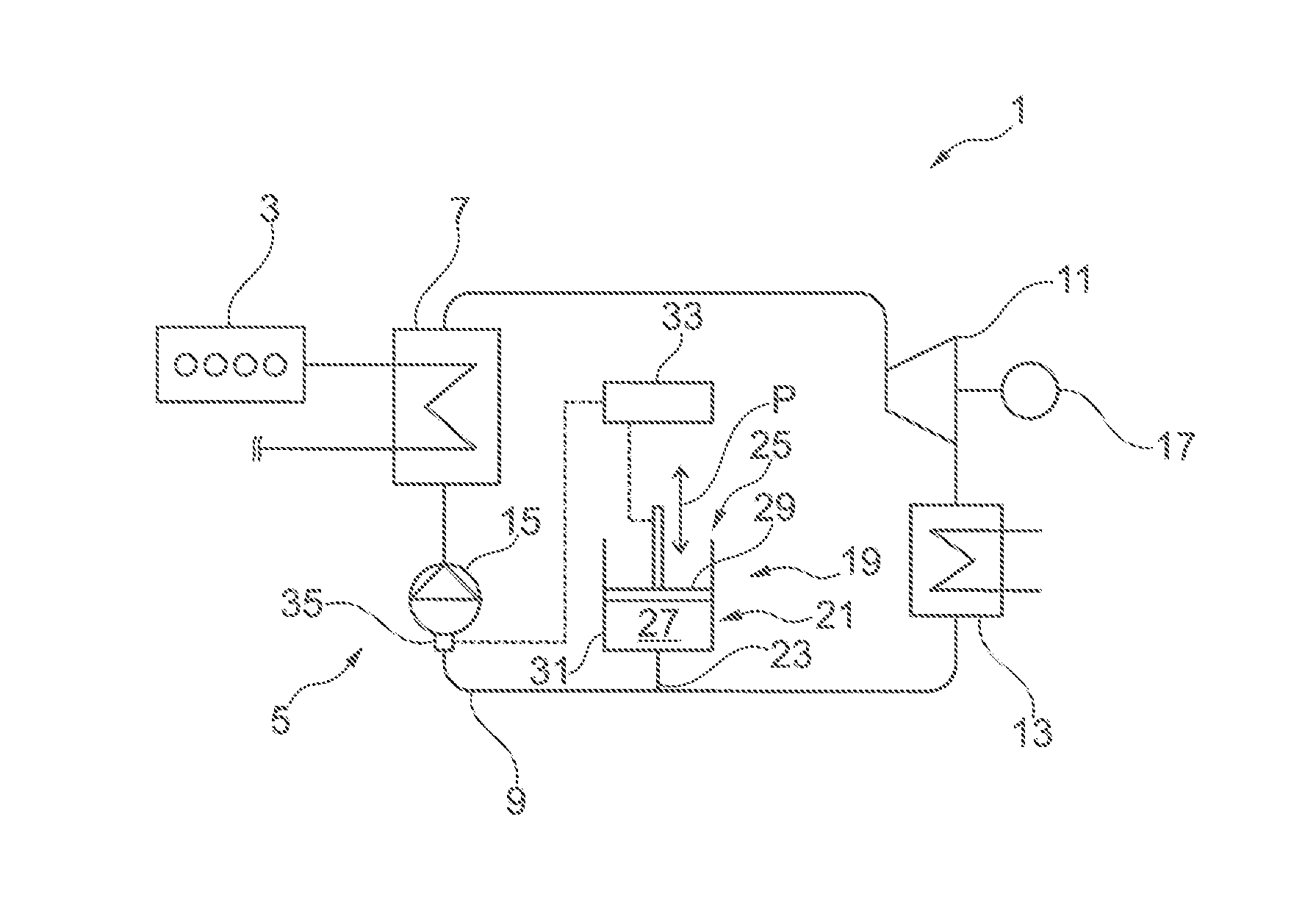
[0041]FIG. 1 shows a first exemplary embodiment of an arrangement 1 with an internal combustion engine 3 and a first exemplary embodiment of a system 5 for operating a thermodynamic cycle, here in particular an organic Rankine cycle. The system 5 and the internal combustion engine 3 are functionally connected to each other for the use of waste heat of the internal combustion engine 3. Waste heat contained in the exhaust gas of the internal combustion engine 3 and / or in the coolant of the internal combustion engine 3 can be supplied to the system 5. An exhaust gas line and / or a coolant line of the internal combustion engine 3 is for this purpose thermally coupled to a evaporator 7 in order to transfer the waste heat of the internal combustion engine 3 to the working medium in the evaporator 7 of the system 5 as the working medium circulates around the circuit 9.

[0042]Arranged in series along the circuit 9 in the flow direction of the working medium, the system 5 comprises the evapora...


PUM


Abstract

A system for a thermodynamic cycle with a circuit for a working medium, wherein a medium quantity-variation device is provided, which is connected to the circuit in such a way and so configured that the quantity of working medium present in the circuit is changeable by the medium quantity-variation device during the operation of the system.

Description

CROSS-REFERENCE TO RELATED APPLICATIONS[0001]The present application claims priority of DE 10 2014 206 038.9, filed Mar. 31, 2014, the priority of this application is hereby claimed and this application is incorporated herein by reference.BACKGROUND OF THE INVENTION[0002]The invention pertains to a system for a thermodynamic cycle, to a control unit for a system for a thermodynamic cycle, to a method for operating such a system, and to an arrangement with an internal combustion engine and such a system.[0003]Systems of the type in question here are known in principle. They comprise a circuit for a working medium, the circuit typically being configured as a closed system with a permanently fixed content of working medium. Such systems can be configured to carry out an organic Rankine cycle, which is similar to the Clausius-Rankine cycle but operates with an organic working medium at lower working temperatures, as a result of which it is especially adapted to the use of waste heat; sy...

Claims


Application Information

Patent Timeline
IPC IPC(8): F02D15/02F02B75/04F02D28/00
CPCF02D15/02F02B75/04F02D28/00F01K13/02F01K23/065F01K23/101F01K25/08F22B1/1807Y02E20/30Y02T10/12
Inventor FAST, GERALDHORBACH, TIMLORENZ, MAXNIEMEYER, JENSSTECHER, DANIELWAIBEL, NIKLASMULLER, MATHIAS
Owner MOTOREN & TURBINEN UNION FRIEDRICHSHAFEN GMBH
Why Eureka
Try Eureka