Wavelength-locking a ring-resonator filter

a ring-resonator filter and wavelength lock technology, applied in the field of optical signal communication techniques, can solve the problems of wdm multiplexer/demultiplexer remains, wdm silicon-photonic implementation obstacle, and variations in the index of refraction

Active Publication Date: 2015-10-01
ORACLE INT CORP
View PDF3 Cites 35 Cited by
  • Summary
  • Abstract
  • Description
  • Claims
  • Application Information

AI Technical Summary

Benefits of technology

[0011]One embodiment of the present disclosure provides an optical device that includes: an input optical waveguide that conveys an input optical signal that includes multiple wavelengths; a ring resonator, having a resonance wavelength, optically coupled to the input optical waveguide; an output optical waveguide that conveys an output optical signal that includes a wavelength in the multiple wavelengths; a monitoring mechanism, optically coupled to the output optical waveguide, which monitors the output optical signal; and control logic that adjusts the resonance wavelength based on the monitored output optical signal, where the adjustment is made without monitoring the input optical signal.

Problems solved by technology

However, a suitable WDM multiplexer / demultiplexer remains a challenge, the lack of which poses an obstacle to implementing WDM silicon-photonic links.
However, one well-known challenge for practical application of a ring-resonator multiplexer / demultiplexer is the uncertainty in the channel spacing and center wavelength that results from variations in the index of refraction of the effective silicon optical waveguide due to fabrication tolerances and ambient temperature change.
However, it can be difficult to accurately sense the ring-resonator temperature.
Consequently, temperature control with sub-Kelvin accuracy is often difficult and typically results in significant power consumption.
Consequently, the electrical controller cannot determine the exact power fluctuation of any given channel, which makes it more difficult for the electrical controller to tune the ring-resonator filters.

Method used


Image

  • Wavelength-locking a ring-resonator filter
  • Wavelength-locking a ring-resonator filter
  • Wavelength-locking a ring-resonator filter

Examples


Embodiment Construction

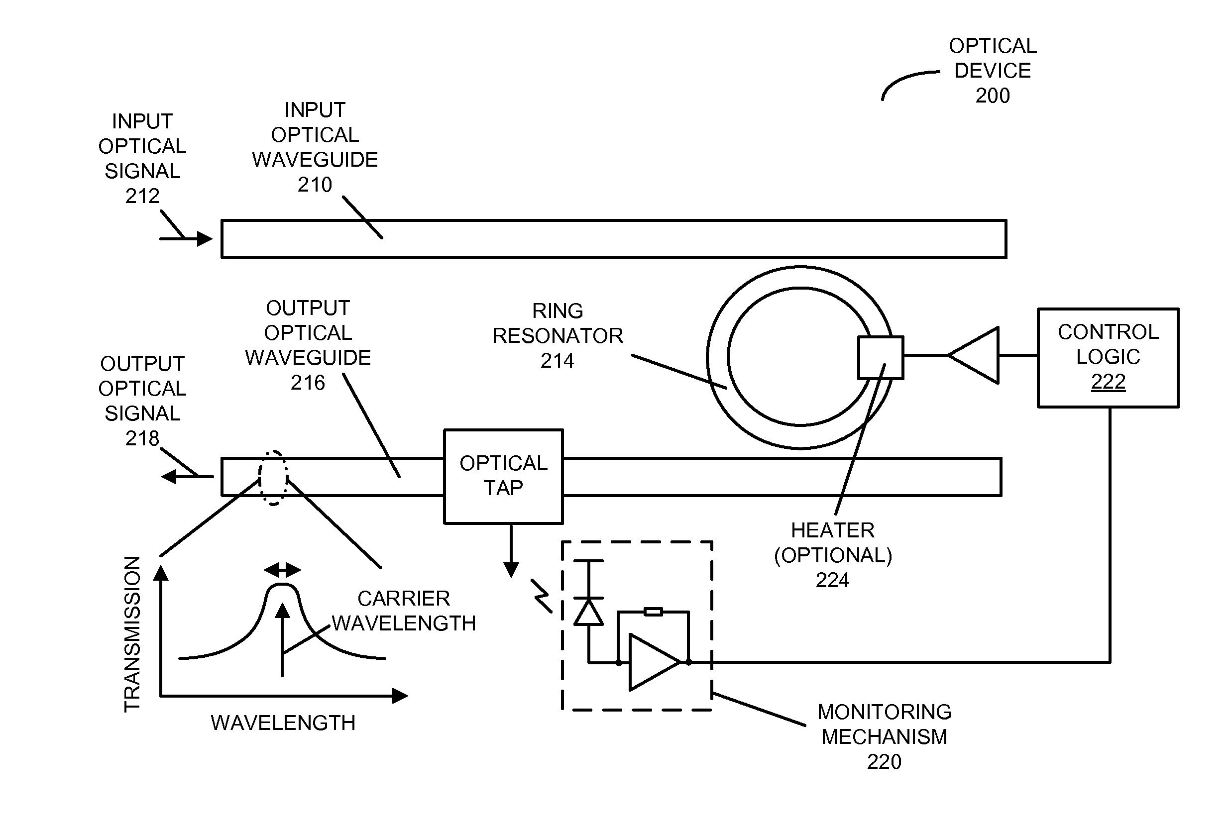
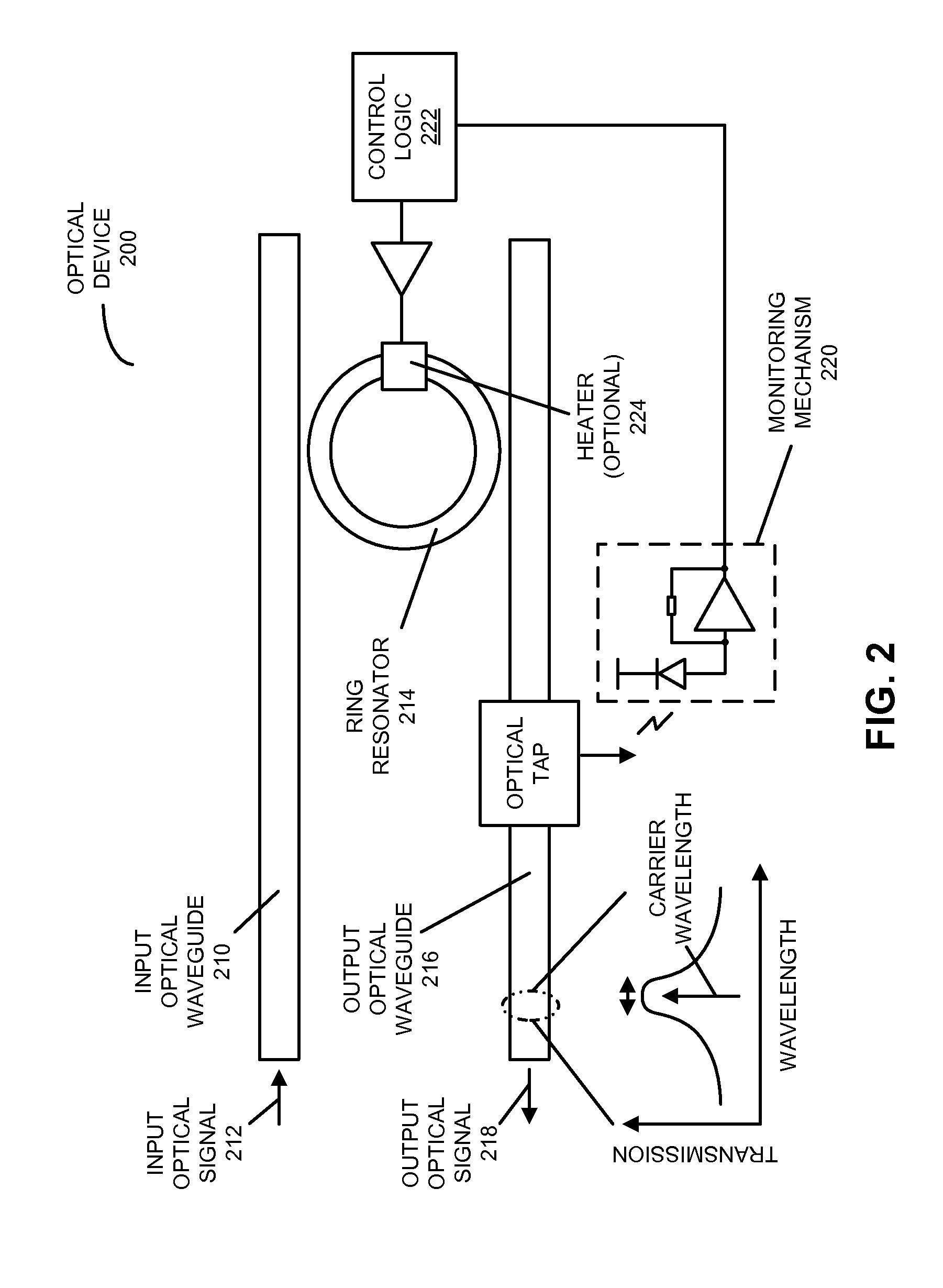
[0026]Embodiments of an optical device, a system that includes the optical device, and a technique for locking a resonance wavelength of a ring resonator to a wavelength of an optical signal are described. In an optical device, the ring resonator, having a resonance (center) wavelength, optically couples the optical signal that includes the wavelength from an input optical waveguide to an output optical waveguide. A monitoring mechanism in the optical device, which is optically coupled to the output optical waveguide, monitors an output optical signal on the output optical waveguide. For example, the monitoring mechanism may dither a temperature of the ring resonator at a frequency using a heater, and the output optical signal may be monitored by determining amplitude and phase information of the output optical signal at the frequency and twice the frequency. Moreover, control logic in the optical device adjusts the resonance wavelength based on the monitored output optical signal, ...


PUM


Abstract

In an optical device, a ring resonator, having a resonance wavelength, optically couples an optical signal that includes a wavelength from an input optical waveguide to an output optical waveguide. A monitoring mechanism in the optical device, which is optically coupled to the output optical waveguide, monitors an output optical signal on the output optical waveguide. For example, the monitoring mechanism may dither a temperature of the ring resonator at a frequency using a heater, and the output optical signal may be monitored by determining amplitude and phase information of the output optical signal at the frequency and twice the frequency. Moreover, control logic in the optical device adjusts the resonance wavelength based on the monitored output optical signal, where the adjustment is made without monitoring an input optical signal on the input optical waveguide.

Description

GOVERNMENT LICENSE RIGHTS[0001]This invention was made with United States government support under Agreement No. HR0011-08-9-0001 awarded by DARPA. The United States government has certain rights in the invention.BACKGROUND[0002]1. Field[0003]The present disclosure relates to techniques for communicating optical signals. More specifically, the present disclosure relates to wavelength-locking a ring-resonator filter without monitoring an input optical signal to the ring-resonator filter.[0004]2. Related Art[0005]Silicon photonics is a promising technology that can provide large communication bandwidth, low latency and low power consumption for inter-chip and intra-chip connections. In the last few years, significant progress has been made in developing low-cost components for use in inter-chip and intra-chip silicon-photonic connections, including: high-bandwidth efficient silicon modulators, low-loss optical waveguides, wavelength-division-multiplexing (WDM) components, and high-spe...

Claims


Application Information

Patent Timeline
Patent Type & Authority Applications(United States)
IPC IPC(8): G02B6/293
CPCG02B6/29383G02B6/29341G02B6/2852G02F1/3132H04J14/00
Inventor ZHENG, XUEZHELI, GUOLIANGLUO, YING L.KRISHNAMOORTHY, ASHOK V.
Owner ORACLE INT CORP
Why Eureka
Try Eureka