
Method for determining a state of obstruction of at least one camera installed in a stereoscopic system

a stereoscopic system and state of obstruction technology, applied in image analysis, image enhancement, instruments, etc., can solve the problems of low accuracy of local methods, high error rate of local methods, and limited performance of camera obstruction detection according to this method, so as to improve the performance characteristics of determination, low error rate, and high density

Active Publication Date: 2015-10-01
CONTINENTAL AUTOMOTIVE FRANCE +1
View PDF2 Cites 8 Cited by
  • Summary
  • Abstract
  • Description
  • Claims
  • Application Information

AI Technical Summary

Benefits of technology

The invention is a hybrid method of determining if there is an obstruction in a stereoscopic system with two cameras. It uses individual disparity maps based on a breakdown of the images into sectors in a direct semi-global analysis, without using an energy function. The method also involves a weighted average of the probabilities of obscuring of the sectors based on their position within the disparity map. This method offers faster decision-making, better obstruction detection, and higher accuracy compared to other methods using cameras. The processing and memory resources required for the method are reasonable, making it easy to install onboard.

Problems solved by technology

It should be noted that a frequent cause of obstruction is the condensation of water on the optics of the camera.
In general, a detection of obstruction leads to warning the driver of the presence of such condensation and may trigger demisting / defrosting means.
The detection of the camera obstruction according to this method only offers limited performances: a partial obstruction of the camera is only detected in 75% of cases, the average distance for carrying out this detection being 200 meters.
The problem is to correctly match the pixels of the left and right images.
However, these local methods suffer from a high error rate, notably in the areas of occlusion and in the areas with little texture—for example for a new road.
They are, however, complex to implement and require very significant processing and memory resources which are not very compatible with the onboard hardware constraints.
The breakdown of the problem of optimization of the energy function into subproblems allows the requirements in processing and memory resources to be decreased with respect to the global methods, but leads to the recurrence of the appearance of artifacts on the disparity map, with a non-negligible error rate and an average—to mediocre-density disparity map (which results from the presence of artifacts).

Method used


Image

  • Method for determining a state of obstruction of at least one camera installed in a stereoscopic system
  • Method for determining a state of obstruction of at least one camera installed in a stereoscopic system
  • Method for determining a state of obstruction of at least one camera installed in a stereoscopic system

Examples


Embodiment Construction

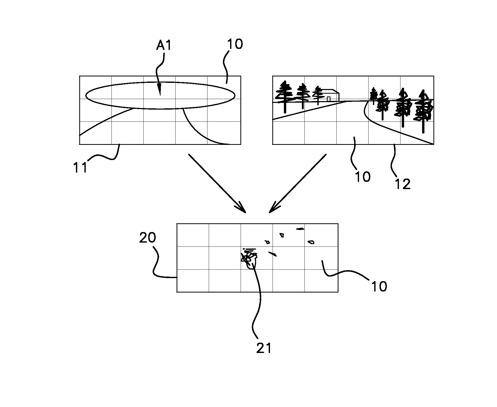
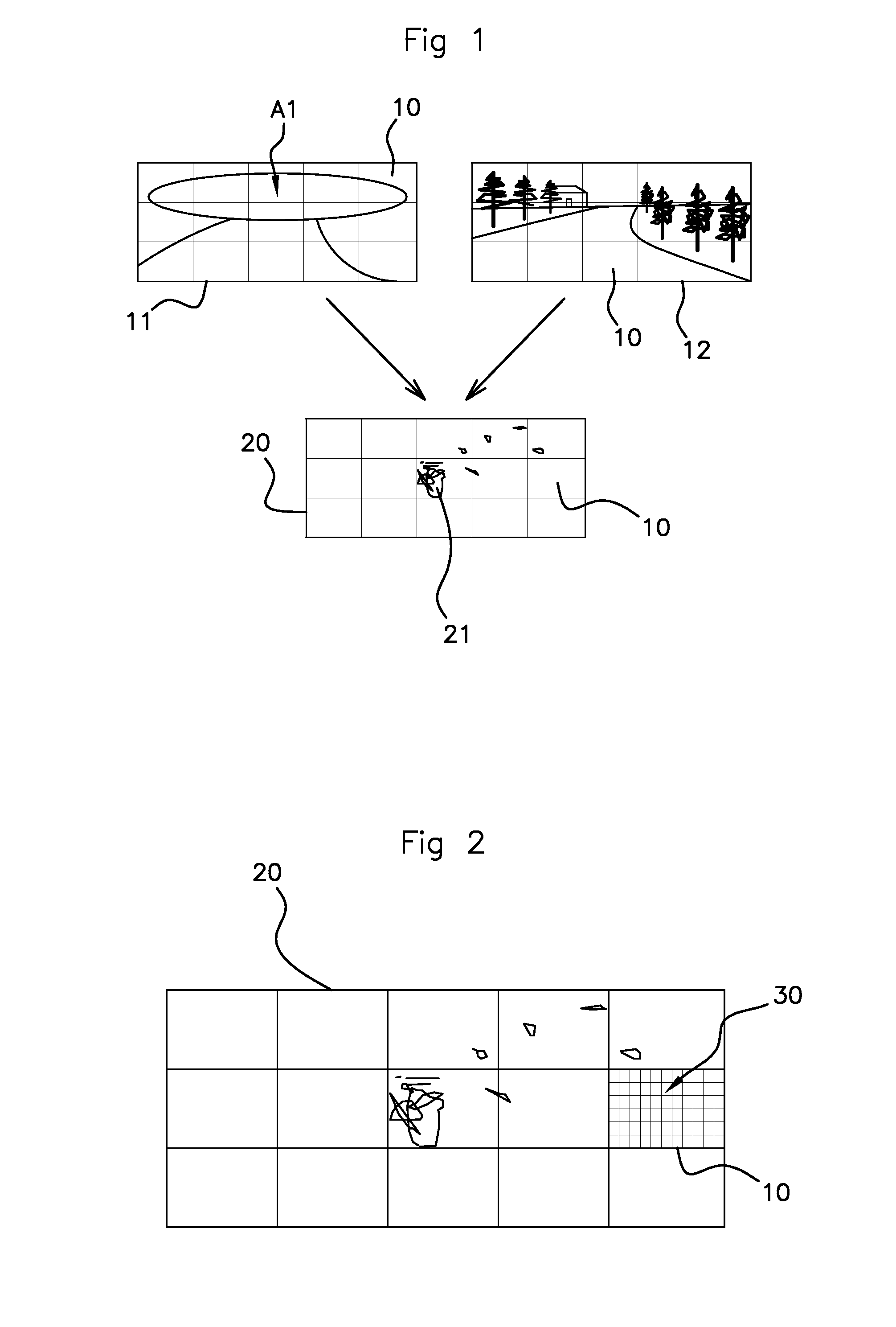
[0050]FIG. 1 illustrates one example of left 11 and right 12 images received on the cameras of a stereoscopic display system on board an automobile vehicle. The disparity map 20 generated by a digital processing system (not shown) from these images 11 and 12 is also shown. The images 11, 12 are divided up into 5×3 regular sectors 10 and the disparity map 20 is accordingly divided into 5×3 sectors. Alternatively, it is possible directly divide up the disparity map into sectors.

[0051]The right image 12 is complete, whereas it would appear that the left image 11 does not reproduce at least the upper region of interest A1 seen on the right image 12. The field of view of the left camera corresponding to the image 11 is thus partially obscured over this upper region A1 which covers the five upper sectors.

[0052]The disparity map 20 is determined by transfer of the disparities by sector10 based on the pixels of one of the images serving as a reference, here the left-hand image 11. Each disp...


PUM


Abstract

To improve the performance for determining obstruction of a stereoscopic system using two cameras or more, a hybrid of local and semi-global methods is provided. For each stereoscopic image formed from simultaneous left and right images, a breakdown of each left and right image into corresponding sectors is applied. Obstruction level is determined by a disparity map by sector, based on left or right images, and in which a disparity is assigned to each pixel corresponding to the best matching score. A determination of density by sector of the disparity map is carried out by reference to a fraction of pixels with a disparity considered to be valid. A state of obstruction of at least one camera is determined based on a weighted average of the probabilities of obscuring of the sectors of the disparity map obtained by comparison between the density of the sectors and a predefined density level.

Description

FIELD OF THE INVENTION[0001]The present invention relates to a method for determining a state of obstruction, also referred to as blockage, of at least one camera in a stereoscopic system installed on board a vehicle, in particular an automobile vehicle, and contributing to assisting the driver of the vehicle in his / her driving.BACKGROUND OF THE INVENTION[0002]In the field of automobile safety and driving assistance, video systems carried on board vehicles are used for the detection of obstacles—objects or persons—or of events outside this vehicle. Using two onboard cameras, the video system managed by a digital processing system allows the distance between the vehicle and these obstacles to be determined. It is then possible to undertake various functionalities, for example: the detection of obstacles, the detection of hazards, the detection and the recognition of road signs, the continuous white line not to be crossed, or else the detection of cars coming from the other direction....

Claims


Application Information

Patent Timeline
Patent Type & Authority Applications(United States)
IPC IPC(8): G06T7/00H04N13/02G06V10/98
CPCG06T7/002H04N13/0285G06T7/0061G06T7/0002G06T2207/10012G06T2207/20021G06T2207/30168G06T2207/30252G06T2207/20076H04N13/286G06V10/98G06T2207/20221
Inventor BAJARD, LAUREGIRALT, ALAINRONY, SOPHIEBARATOFF, GREGORY
Owner CONTINENTAL AUTOMOTIVE FRANCE
Learn More