Piezoelectric element
a technology of electric elements and piezoelectric elements, applied in the direction of generators/motors, input/output processes of data processing, instruments, etc., can solve the problems of insufficient electric output, insufficient electric output, difficult to extract sufficient electric output, etc., and achieve the effect of simply extracting electric outpu
- Summary
- Abstract
- Description
- Claims
- Application Information
AI Technical Summary
Benefits of technology
Problems solved by technology
Method used
Image

Examples
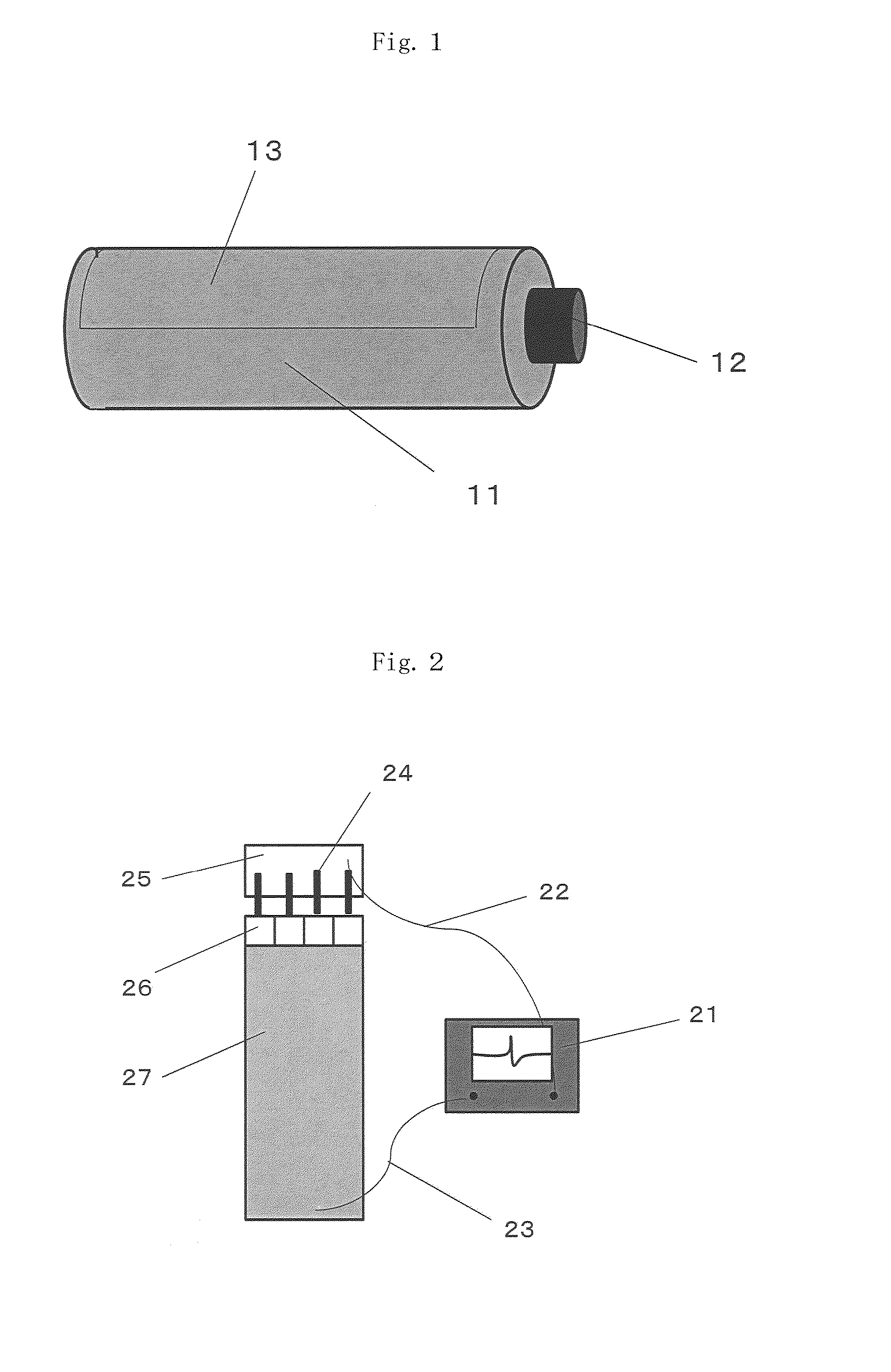
embodiment 1
Another Embodiment 1 of Piezoelectric Element
[0088]The piezoelectric element of the present invention includes the following piezoelectric element as another embodiment.[0089]1. A piezoelectric element including a conductive fiber, a piezoelectric polymer which covers the surface of the conductive fiber and a surface conductive layer formed on the surface of the piezoelectric polymer.[0090]2. The piezoelectric element in the above paragraph 1, wherein the piezoelectric polymer comprises polylactic acid as the main component.[0091]3. The piezoelectric element in the above paragraph 1 or 2, wherein the piezoelectric polymer comprises poly-L-lactic acid or poly-D-lactic acid as the main component, and the optical purities of these components are 99% or more.[0092]4. The piezoelectric element in the above paragraph 2 or 3, wherein the piezoelectric polymer is uniaxially oriented and contains a crystal.[0093]5. The piezoelectric element in any one of the above paragraphs 1 to 4, wherein ...
embodiment 2
Another Embodiment 2 of Piezoelectric Element
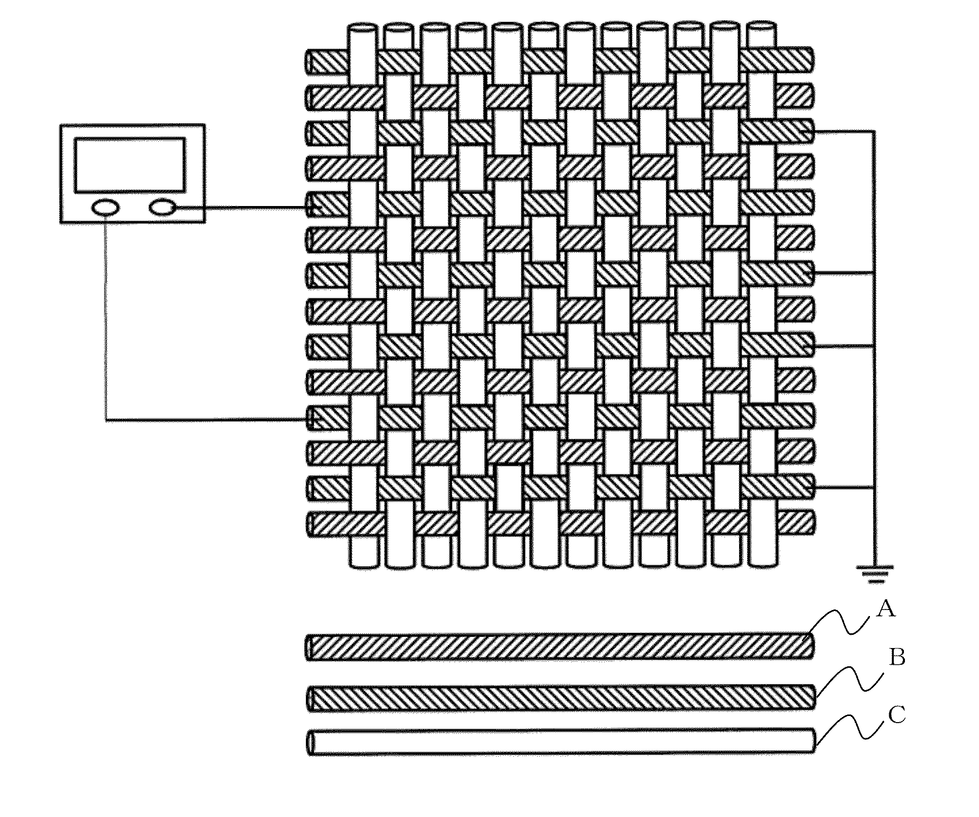
[0122]The piezoelectric element of the present invention includes the following piezoelectric element as another embodiment.[0123]1. A piezoelectric element includes at least two covered fibers which are prepared by covering the surfaces of conductive fibers with a piezoelectric polymer and are arranged substantially parallel to each other, wherein the piezoelectric polymers on the surfaces are in contact with each other.[0124]2. The piezoelectric element in the above paragraph 1, wherein the piezoelectric polymer comprises polylactic acid as the main component.[0125]3. The piezoelectric element in the above paragraph 1 or 2, wherein the piezoelectric polymer comprises poly-L-lactic acid or poly-D-lactic acid as the main component and the optical purities of these components are 99% or more.[0126]4. The piezoelectric element in any one of the above paragraphs 1 to 3, wherein the piezoelectric polymer is uniaxially oriented and contains a ...
example 1
(Production of Polylactic Acid)
[0173]0.005 part by weight of tin octylate was added to 100 parts by weight of L-lactide (manufactured by Musashino Chemical Laboratory, Ltd., optical purity of 100%) to carry out a reaction in a nitrogen atmosphere at 180° C. for 2 hours in a reactor equipped with a stirring blade, phosphoric acid was added in an amount which was 1.2 times the equivalent of tin octylate, the residual lactide was removed under a reduced pressure of 13.3 Pa, and the resulting product was formed into a chip to obtain poly-L-lactic acid (PLLA1). The obtained PLLA1 had a weight average molecular weight of 152,000, a glass transition point (Tg) of 55° C. and a melting point of 175° C.
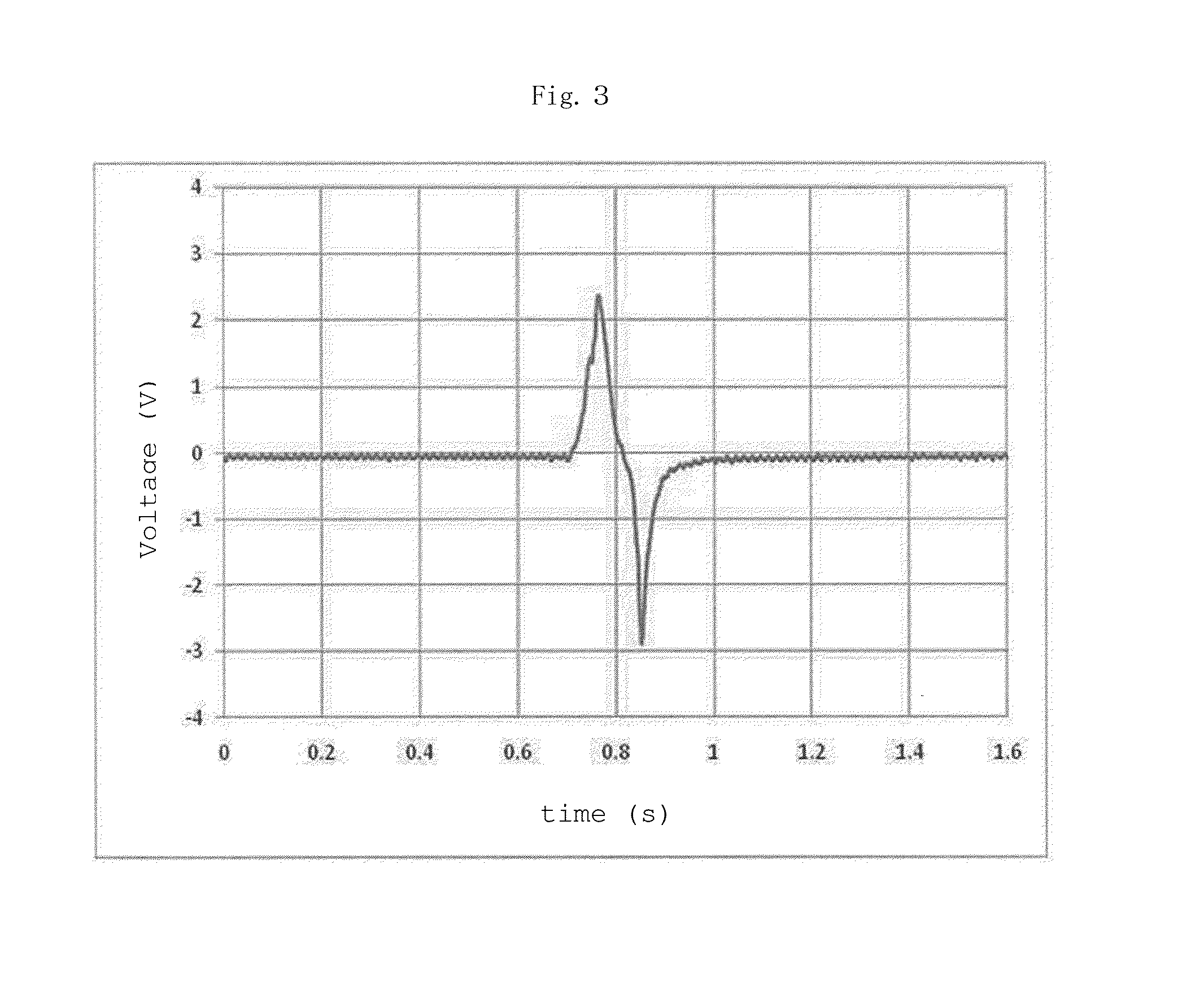
(Evaluation of Piezoelectric Element)
[0174]The piezoelectric element was evaluated as follows in Example 1.
[0175]A finger was caused to touch the surface (gold deposited surface) of a surface conductive layer and to rub the surface at a velocity of about 0.5 m / s in a direction parallel to the l...
PUM
 Abstract
Description
Claims
Application Information