
Chemical mechanical polishing conditioner having different heights

a technology of mechanical polishing conditioner and height, which is applied in the direction of grinding drive, abrasive surface conditioning device, manufacturing tool, etc., can solve the problems of reducing the polishing effect and efficiency, scratching, local over-polishing, etc., to improve the drainage of abrasive slurry, improve the uniformity of polishing, and prevent thermal deformation of the substrate

Inactive Publication Date: 2015-10-08
KINIK
View PDF4 Cites 13 Cited by
  • Summary
  • Abstract
  • Description
  • Claims
  • Application Information

AI Technical Summary

Benefits of technology

The invention provides a CMP conditioner that has different heights by combining small abrasive units with a large substrate. This results in a surface with improved polishing uniformity and different heights of the abrasive units, which prevents thermal deformation of the substrate and produces different piercing depths. The conditioner also adjusts surface roughness, improves drainage of abrasive slurry, and makes the pad a uniform surface after polishing. A middle layer made of aluminum oxide, silicon carbide, or aluminum nitride is used to improve binding strength between the abrasive layer and the substrate. This non-uniform configuration in height helps to achieve a uniform surface after polishing.

Problems solved by technology

When the pad has been used for a period of time, polishing debris produced from the CMP process will accumulate and stagnate on the surface of the pad, thereby reducing the polishing effect and efficiency.
Said CMP conditioner is suitable for dressing the pads; however, in more sophisticated semiconductor process with line-width below 45 nanometers, the rough surface of the pad that is too coarse will cause problems such as scratch, local over-polishing, depression, or non-uniform thickness of the wafer.
However, the protrusions and the substrate are integrally formed, failing to form a totally planarized surface to improve the abrasion efficiency and prolong lifetime of the CMP conditioner.
However, when the pad conditioner is applied to a pad, the pad conditioner cannot control an abrasion depth of the pad.
Furthermore, the abrasive ability of a conventional CMP conditioner is limited by the crystal structure of the abrasive particles.

Method used


Image

  • Chemical mechanical polishing conditioner having different heights
  • Chemical mechanical polishing conditioner having different heights
  • Chemical mechanical polishing conditioner having different heights

Examples


embodiment 1

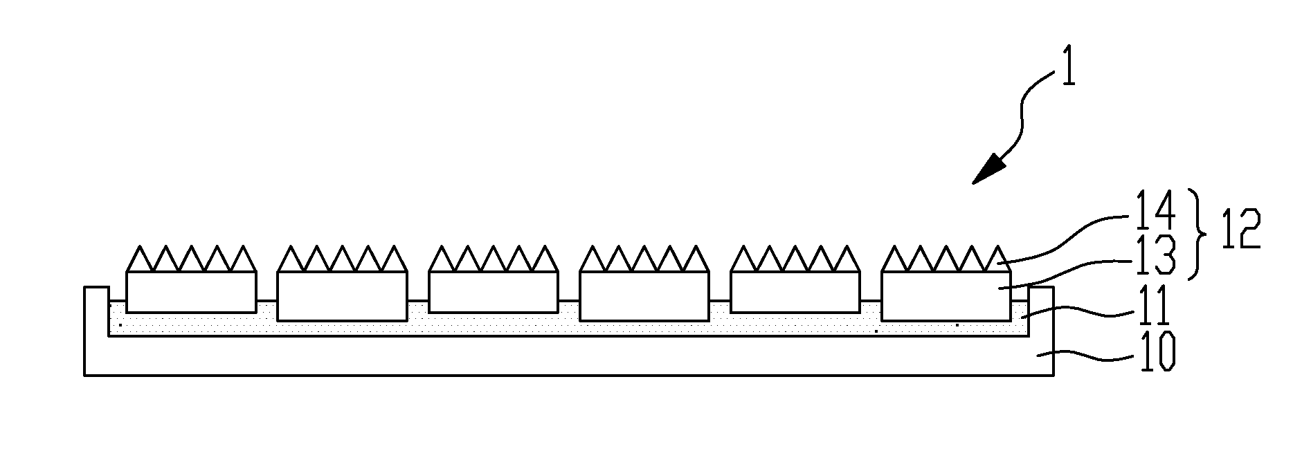
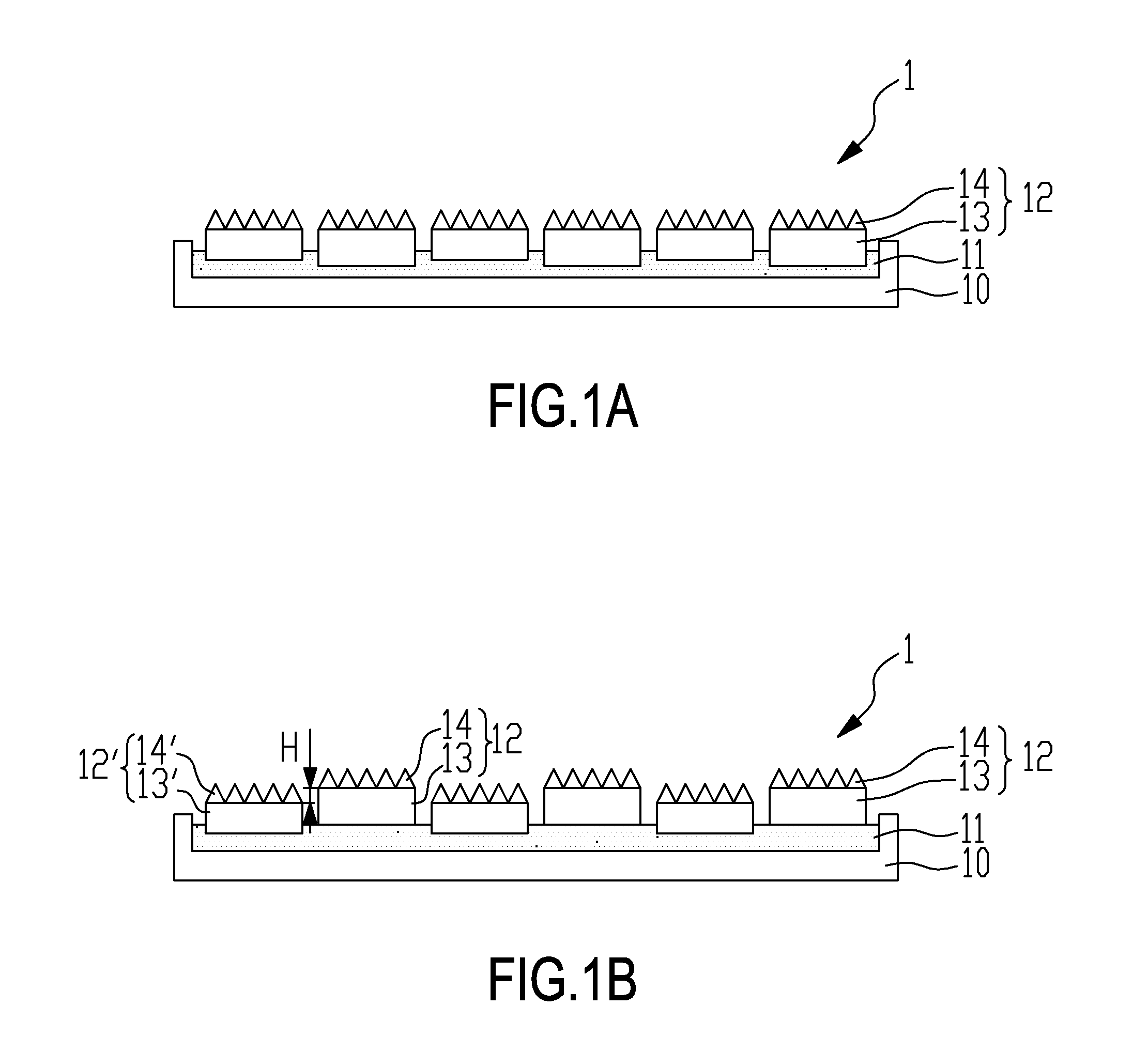
[0036]With reference to FIG. 1A, the present invention provides a chemical mechanical polishing conditioner having different heights 1. The chemical mechanical polishing conditioner having different heights 1 comprises a substrate 10 made of stainless steel, a binding layer 11, and multiple abrasive units 12. The substrate 10 is a flat substrate and has a thickness of 80 mm. The binding layer 11 is disposed on the substrate 10. Each abrasive unit 12 has an abrasive unit substrate 13 and an abrasive layer 14. The abrasive unit substrate 13 is a ceramic substrate made of silicon carbide. The abrasive unit substrates 13 have two different thicknesses, 20 mm and 30 mm. A surface of the abrasive unit substrate 13 is a flat surface and the abrasive layer 14 is successively formed on the surface tips by chemical vapor deposition to obtain multiple abrasive tips. The abrasive tips are in the shape of pyramids. Specifically, with reference to FIG. 5A, the abrasive tips are continuously arran...

embodiment 2

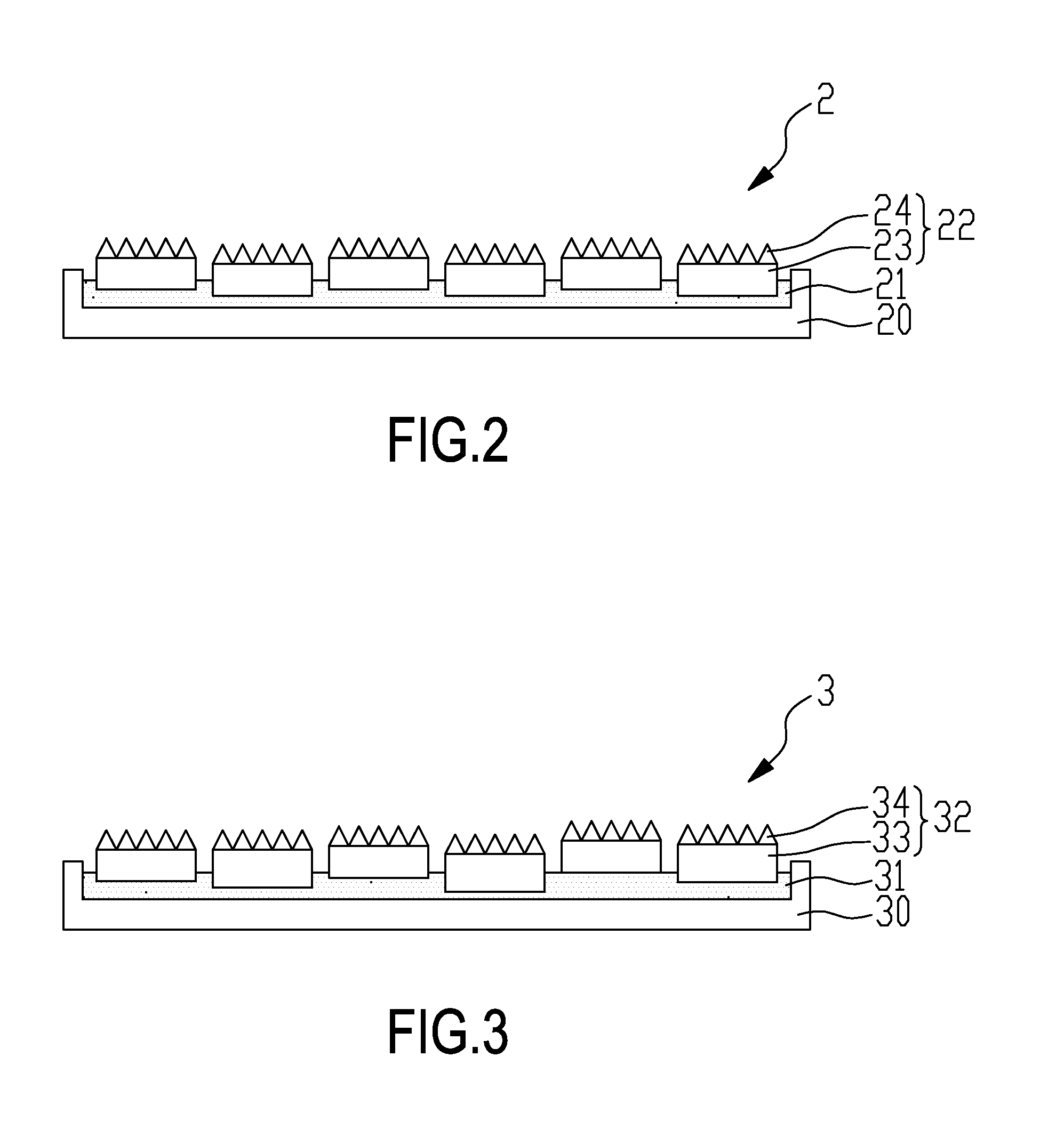
[0037]With reference to FIG. 2, the CMP conditioner having different heights 2 in Embodiment 2 is similar with the CMP conditioner having different heights in Embodiment 1. The difference between the two embodiments is that the thicknesses of the abrasive units of the CMP conditioner having different heights in Embodiment 1 are different and the thickness of the binding layer of the CMP conditioner having different heights in Embodiment 1 is fixed. However, the thicknesses of the abrasive units of the CMP conditioner having different heights in Embodiment 2 are equal and thickness of the binding layer of the CMP conditioner having different heights in Embodiment 2 is varied. The CMP conditioner having different heights 2 of the present embodiment comprises the substrate 20 made of stainless steel, the binding layer 21, and the abrasive units 22. The substrate 20 is a flat substrate and has a thickness of 80 mm. The binding layer 21 is disposed on the substrate 20. Each abrasive unit...

embodiment 3

[0038]With reference to FIG. 3, the CMP conditioner having different heights 3 in Embodiment 3 is similar with the CMP conditioner having different heights in Embodiment 1. The difference between the two embodiments is that thicknesses of the abrasive units of the CMP conditioner having different heights in Embodiment 1 are different and thickness of the binding layer of the CMP conditioner having different heights in Embodiment 1 is fixed. However, the thicknesses of the abrasive units of the CMP conditioner having different heights in Embodiment 3 are different and the thickness of the binding layer of the CMP conditioner having different heights in Embodiment 3 is varied. The CMP conditioner having different heights 3 of the present embodiment comprises the substrate 30 made of stainless steel, the binding layer 31, and the abrasive units 32. The substrate 30 is a flat substrate and has a thickness of 80 mm. The binding layer 31 is disposed on the substrate 30. Each abrasive unit...


PUM

PropertyMeasurementUnit
heightaaaaaaaaaa
heightaaaaaaaaaa
thicknessaaaaaaaaaa

Abstract

The present invention relates to a chemical mechanical polishing conditioner having different heights, comprising: a substrate; a binding layer disposed on the substrate; and multiple abrasive units placed on the binding layer. Each abrasive unit has an abrasive unit substrate and an abrasive layer which is a diamond film formed by chemical vapor deposition and has multiple abrasive tips. The abrasive units have a first tip height and a second tip height. The first tip height is different from the second tip height. The chemical mechanical polishing conditioner can adjust the surface roughness of the pad to be polished and improve the drainage of abrasive slurry.

Description

BACKGROUND OF THE INVENTION[0001]1. Field of the Invention[0002]The present invention relates to a chemical mechanical polishing conditioner having different heights, especially to a combinational chemical mechanical polishing conditioner having different heights.[0003]2. Description of the Prior Art(s)[0004]Chemical Mechanical Polishing (abbreviated as CMP) is commonly used in various industries to polish the surfaces of various articles made of ceramic, silicon, glass, quartz, or metal. With the applicability of large-scaled planarization of integrated semiconductor device, CMP becomes a common planarization technique in the semiconductor process.[0005]During the CMP process of the semiconductor, a pad is contacted with a wafer or other semiconductor elements in conjunction with suitable abrasive slurry to remove impurities or protruding structures on the surface of the wafer through both chemical reaction and mechanical force. When the pad has been used for a period of time, poli...

Claims


Application Information

Patent Timeline
Patent Type & Authority Applications(United States)
IPC IPC(8): B24B53/017
CPCB24B53/017
Inventor CHOU, JUI-LINWANG, CHIA-CHUNCHIU, CHIA-FENGLIAO, WEN-JEN
Owner KINIK
Learn More