Near-field magnetic object tracking

a magnetic object and near-field technology, applied in the direction of magnetic sensor geometrical arrangement, electric/magnetic measurement arrangement, point coordinate measurement, etc., can solve the problems of inability to achieve pure dc system, poor performance of ac system in presence of conducting magnetic materials such as carbon steel and other ferrous metals, and inability to achieve high resolution and accuracy

Inactive Publication Date: 2015-10-08
LOWERY ANDREW D +2
View PDF5 Cites 19 Cited by
  • Summary
  • Abstract
  • Description
  • Claims
  • Application Information

AI Technical Summary

Benefits of technology

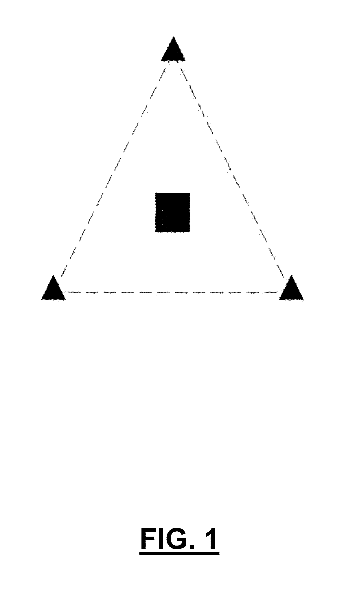
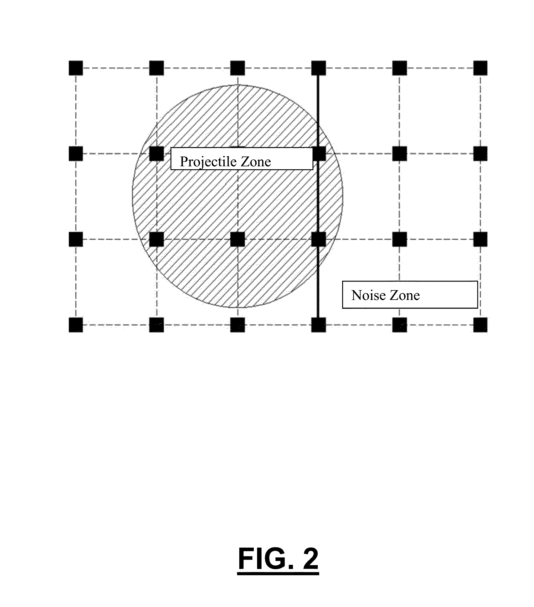
[0010]A system and method utilizing single axis magnetic sensors to locate and track the position and orientation of a magnetic source in three-dimensional space are generally presented. The system may include a sensor grid having a plurality of sensor clusters configured to sense the presence of a magnetic field of an object. Each sensor cluster may comprise three or more single-ax

Problems solved by technology

While magnetic tracking applications have been developed, most such applications are limited by accuracy, cost, size, and especially speed of use (computational limitations).
Generally, AC systems have high resolution and accuracy, but perform very poorly in the presence of conducting magnetic materials such as carbon steel and other ferrous metals.
This is mainly due to the fact that the system's alternating current produces magnetic noise, in the form of eddy currents within those materials or in conjunction with them, which interfere with the final resolution.
It has been sugge

Method used


Image

  • Near-field magnetic object tracking
  • Near-field magnetic object tracking
  • Near-field magnetic object tracking

Examples


Embodiment Construction

[0038]While the invention is described herein with reference to several embodiments, it should be clear that the invention should not be limited only to the embodiments disclosed or discussed. The description of the embodiments herein is illustrative of the invention and should not limit the scope of the invention as described or claimed.

[0039]A method used to locate and track a magnetic source, both position and orientation, in three-dimensional space through a magnetically noisy environment, is generally presented. It is well known that the tracking of moving objects can be accomplished with a strategic arrangement of a multitude of sensors, such as a sensor grid arrangement. For this application, these sensors could be of a single type, such as a magnetic type sensor, or a combinations of different types. One embodiment may be a magnetometer.

[0040]In typical tracking systems, each three-axis sensor and associated signal processing would result in a direction vector or bearing, po...


PUM


Abstract

An object tracking system includes a sensor grid having a plurality of sensor clusters configured to sense the presence of a magnetic field of an object. Each sensor cluster includes three or more single-axis magnetic sensors. The sensors in a cluster may be arranged with their axes parallel to one another. The sensor grid may account for ambient magnetic noise by measuring the magnetic field in a zone a distance away from the object to update the ambient magnetic field noise measurement. The sensor grid or a portion thereof may include a plurality of sensors printed on a common sheet. The sensor grid may comprise one or more sheets overlapped or interconnected. The system may track an object and determine up to three degrees of positioning and three degrees of orientation by using a geometric solution of the intercepts of magnetic field strengths obtained from information collected by the magnetic sensors.

Description

CROSS-REFERENCE TO RELATED APPLICATIONS[0001]This application claims priority to U.S. Provisional Patent Application No. 61 / 816,410 entitled “NEAR-FIELD MAGNETIC OBJECT TRACKING,” filed on Apr. 26, 2013, which is hereby incorporated by reference in its entirety.FIELD OF THE INVENTION[0002]The present invention relates generally to a tracking system, and more particularly, to a system for determining position and orientation of a magnetic source in three-dimensional space from single-axis, co-linear clusters of sensors.BACKGROUND OF THE INVENTION[0003]There is a constant need for technologies capable of tracking an object's position. In the field of transportation, there is a need to track the position of ships, airplanes, vehicles, etc. Military activities have always required the use of position tracking, such as the need to determine the position of a bombing target. Law enforcement agencies frequently need to determine the position of a subject individual or object, such as a pac...

Claims


Application Information

Patent Timeline
IPC IPC(8): G01B7/004
CPCG01B7/004G01R33/0005
Inventor LOWERY, ANDREW D.PERTL, FRANZ A.SMITH, JAMES E.
Owner LOWERY ANDREW D
Why Eureka
Try Eureka