Millimeter waveband filter
- Summary
- Abstract
- Description
- Claims
- Application Information
AI Technical Summary
Benefits of technology
Problems solved by technology
Method used
Image

Examples
Embodiment Construction
[0045]Hereinafter, an embodiment of the invention will be described referring to the drawings.
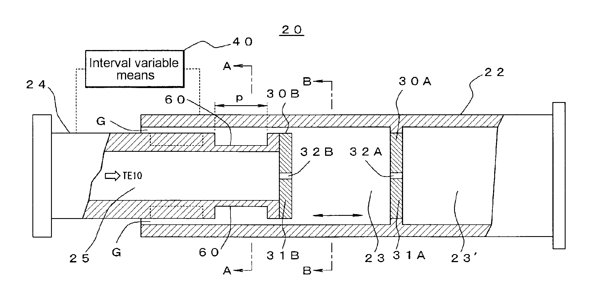
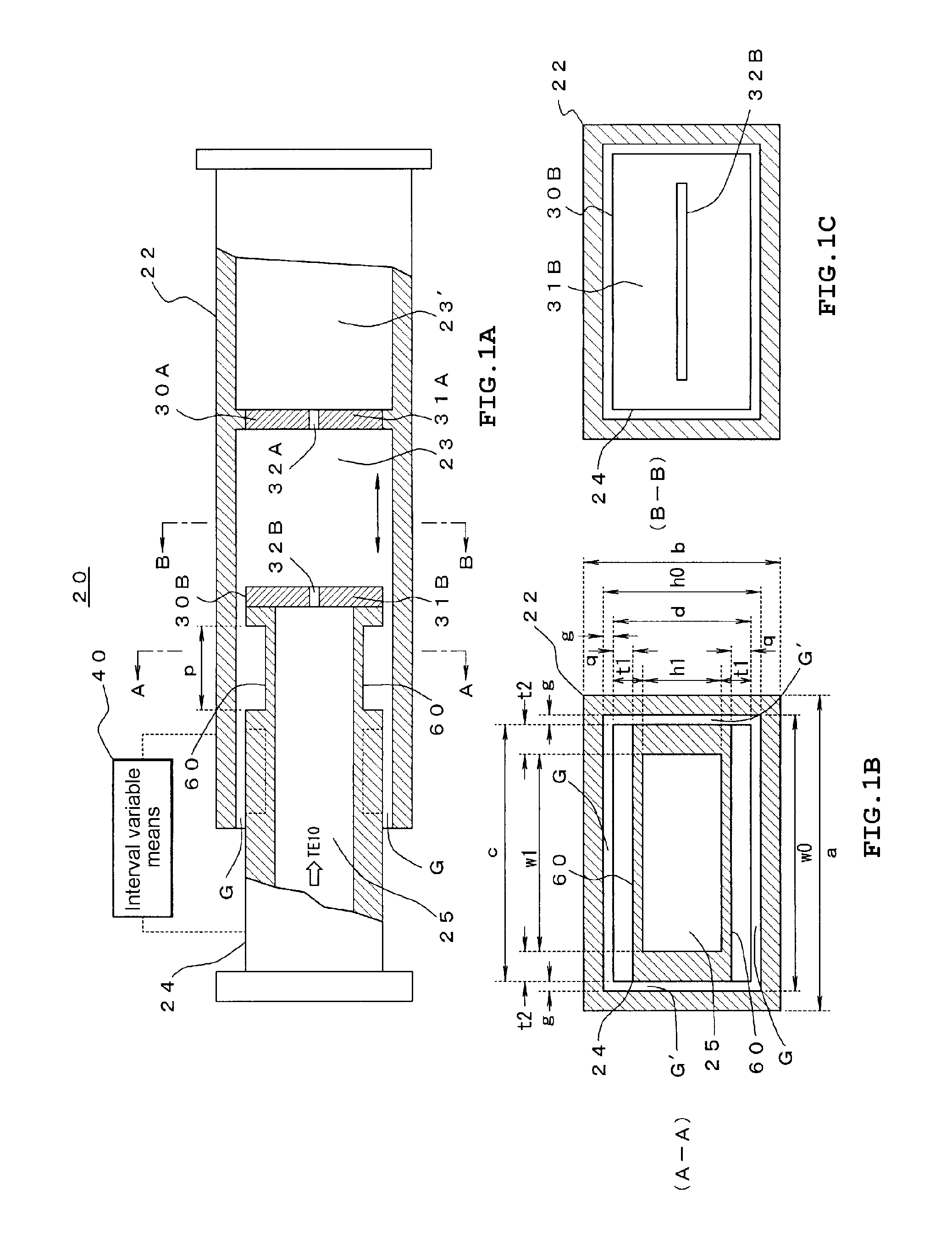
[0046]FIGS. 1A to 1C show the basic structure of a millimeter waveband filter 20 of the invention. FIG. 1A is a diagram when a part of the millimeter waveband filter 20 is fractured from the side, FIG. 1B is a sectional view taken along the line A-A of FIG. 1A, and FIG. 1C is a sectional view taken along the line B-B of FIG. 1A.
[0047]As shown in FIGS. 1A to 1C, the millimeter waveband filter 20 has a first waveguide 22, a second waveguide 24, a pair of electric wave half mirrors 30A and 30B, and interval variable means 40.
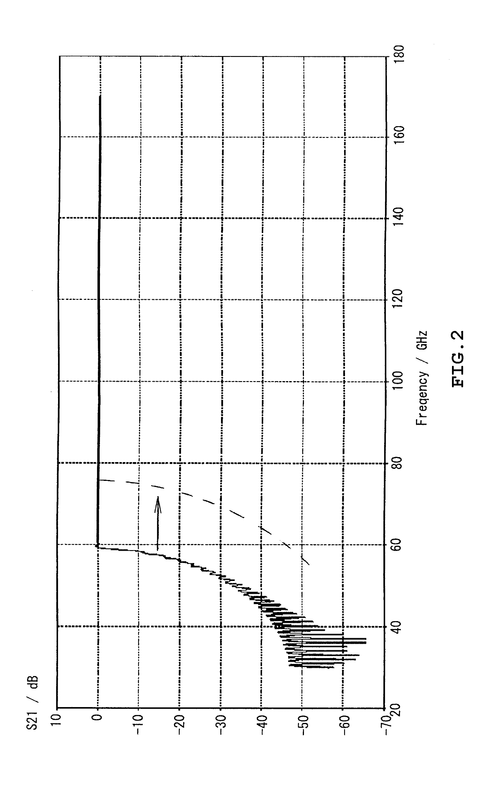
[0048]The first waveguide 22 is a square waveguide which has a transmission line 23 having a rectangular sectional shape allowing electromagnetic waves in a predetermined frequency range (for example, 75 to 110 GHz) of a millimeter waveband to propagate in a TE10 mode (single mode). For example, a WR-10 waveguide having a size of w0×h0=2.54×1.27 mm can be used. In FIGS. 1A...
PUM
 Abstract
Description
Claims
Application Information