Transceiver Element for an Optical Unit of a Photoelectric Barrier and Photoelectric Light Curtain

a technology of transceiver element and photoelectric barrier, which is applied in the direction of optical detection, fibre transmission, transmission, etc., can solve the problems of side lobes or disturbances into adjacent light curtain systems, and achieve the effects of small form factor, reduced unit cost, and full custom capability

Active Publication Date: 2015-10-08
ROCKWELL AUTOMATION SWITZERLAND
View PDF3 Cites 4 Cited by
  • Summary
  • Abstract
  • Description
  • Claims
  • Application Information

AI Technical Summary

Benefits of technology

[0012]According to one aspect of the invention, the control element is fabricated as an integrated circuit, such as an application specific integrated circuit (ASIC). Alternatively, also a field programmable gate array (FPGA) design can be used. As is known to a person skilled in the art, ASICs have the advantage of a full custom capability, lower unit costs and a small form factor, whereas FPGAs have the advantage of a faster time to market and a simpler design cycle.
[0013]According to another aspect of the invention, the driver unit is operable to adjust an emission intensity of the optical sensor in response to a first setting signal. This feature has the advantage that the emitted radiation can be adjusted to different environmental conditions. Furthermore, by being able to operate, for instance, LEDs with an adjustable emitter current, the driver current may, for instance, be adjusted to external or internal temperature, variations, which is highly desirable, because LEDs have a heavily temperature dependent emitting intensity. On the other hand, by directly evaluating the measured incident radiation on the opposing side and sending back an electrical or optical signal indicative of the amount of incident radiation, the emission intensity can be adapted, for instance, for a front window pollution or ambient obscuring effects, such as dust or the like.

Problems solved by technology

Too high intensities would, for example, cause side lobes or disturbances into adjacent light curtain systems.

Method used


Image

  • Transceiver Element for an Optical Unit of a Photoelectric Barrier and Photoelectric Light Curtain
  • Transceiver Element for an Optical Unit of a Photoelectric Barrier and Photoelectric Light Curtain
  • Transceiver Element for an Optical Unit of a Photoelectric Barrier and Photoelectric Light Curtain

Examples


Embodiment Construction

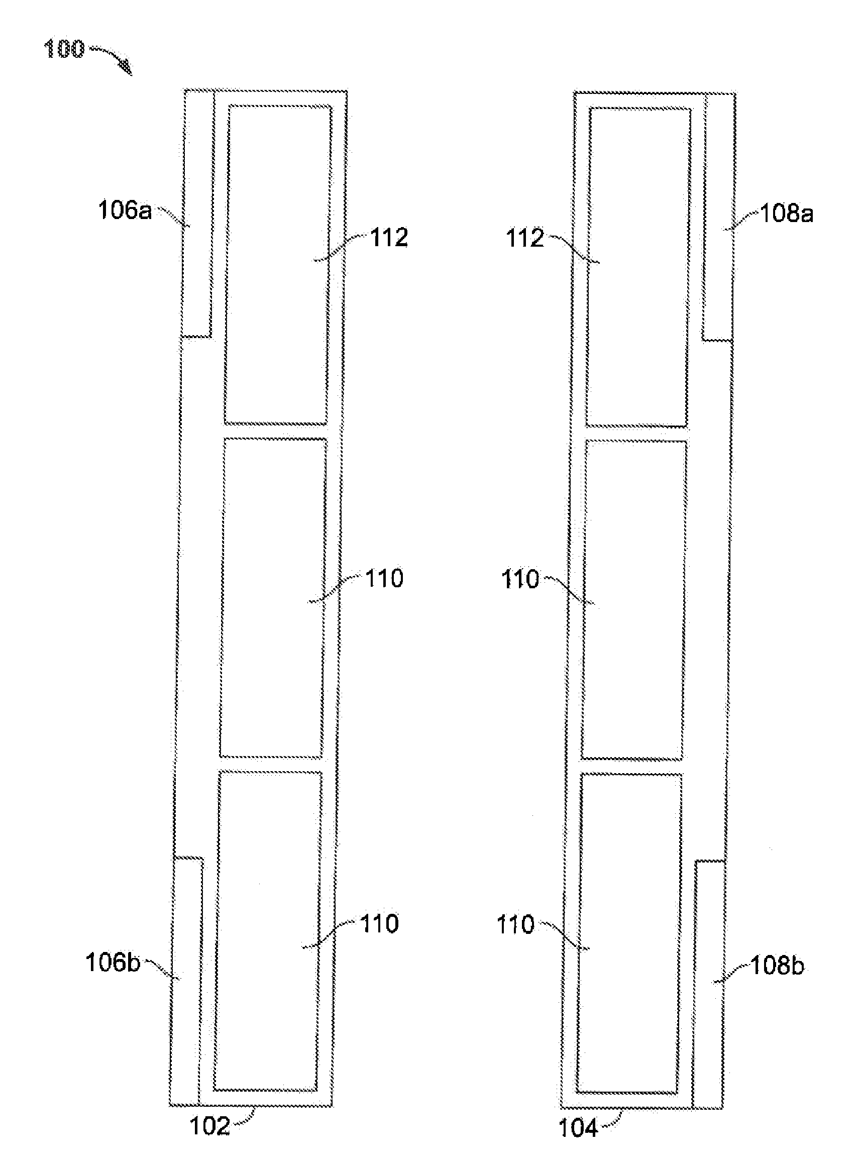
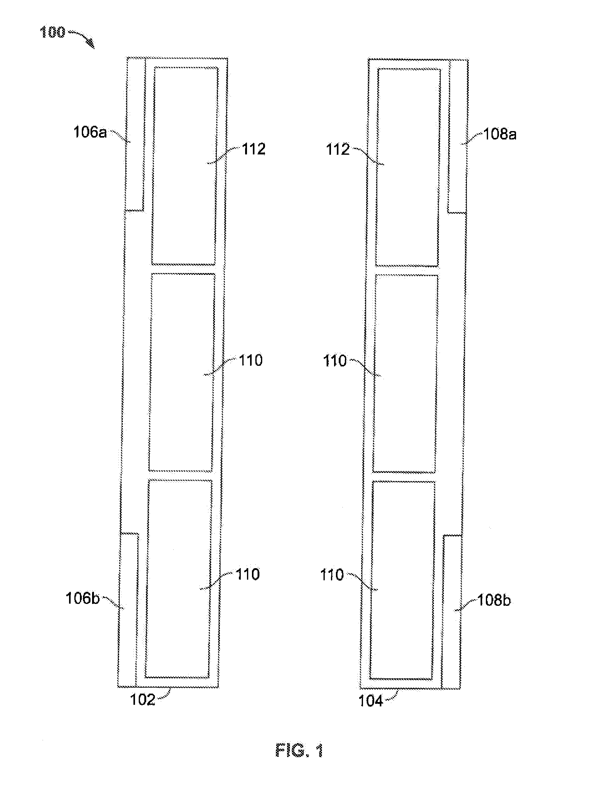
[0043]Referring now to FIG. 1, a schematic representation of a light curtain comprising two optical units is shown.

[0044]The light curtain 100 in this embodiment consists of two identical first and second optical units 102, 104, which form between each other a plurality of light bathers for monitoring a protective field. However, the ideas of the present invention are also applicable in systems which comprise more than two optical units. The optical units 102, 104 may for instance be formed according to the principles of the European patent application EP 2511737 A1, and may in particular use plug-in modules 106, 108 for defining their respective functionality.

[0045]According to the embodiment shown in FIG. 1, each optical unit 102, 104 comprises two identical modules 110 each having light emitting and light receiving elements. These optical nodules 110 are identically built for both optical units 102, 104. Each of the optical units 102, 104 further comprises at least one second opt...


PUM


Abstract

The present invention relates to a transceiver element for an optical unit of a photoelectric barrier to such a photoelectric barrier. In particular, a transceiver element comprises at least one optical sender, at least one optical receiver and a control element, wherein said control element comprises a driver unit for driving said at least one optical sender to emit radiation and at least one receiver unit for sensing and evaluating electrical signals generated by said optical receiver.

Description

CROSS-REFERENCE TO RELATED APPLICATIONS[0001]This application claims priority to European Patent Application No EP 13 169 470.5, filed May 28, 2013, the entire content of which is incorporated herein by reference.BACKGROUND OF THE INVENTION[0002]The subject matter disclosed herein relates generally to light curtains and photoelectric barriers and, more specifically, to safety light curtains for monitoring a protective field. In particular, the present invention relates to a transceiver element for an optical unit of a photoelectric barrier and to such a photoelectric barrier.[0003]Generally, photoelectric barriers, also referred to as light curtains or light grids, detect the movement or intrusion of objects into guarded zones, and more particularly, provide protection for human operators who are working with machines or other industrial equipment. Such photoelectric barriers can be formed by two or more optical units (also called bars, sticks, edges or strips), or by one optical un...

Claims


Application Information

Patent Timeline
Patent Type & Authority Applications(United States)
IPC IPC(8): H04B10/40H04B10/2575H04B10/079
CPCH04B10/40H04B10/2575H04B10/0795G01V8/20
Inventor MEINHERZ, CARLDOGUL, JAMES EDWARDROLLINS, GEORGE E.HARDEGGER, MARTINWALTHER, CHRISTOPHERDORIZZI, DANILO
Owner ROCKWELL AUTOMATION SWITZERLAND
Why Eureka
Try Eureka