
Composite implant coating

a technology of composite materials and implants, applied in the direction of osteosynthesis devices, prosthesis, buttons, etc., can solve the problems of loss of bone support for implants, plate creating relatively high stresses, and affecting the implant life of patients

Active Publication Date: 2015-10-15
CARBOFIX SPINE INC
View PDF13 Cites 21 Cited by
  • Summary
  • Abstract
  • Description
  • Claims
  • Application Information

AI Technical Summary

Benefits of technology

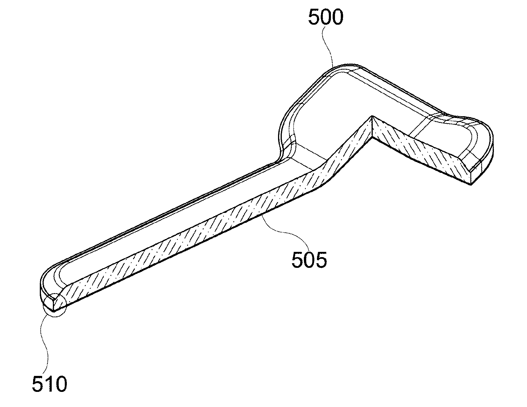
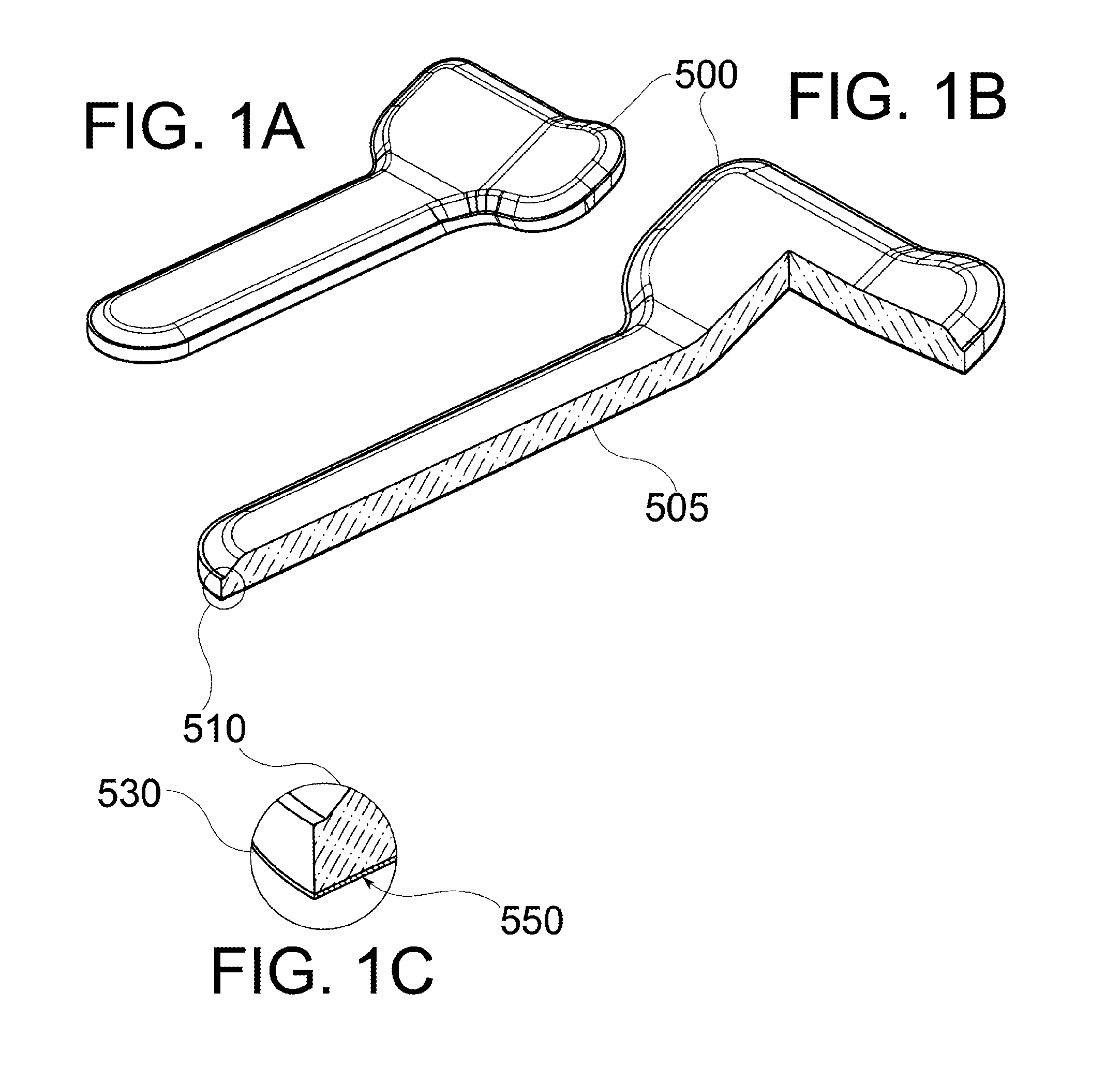
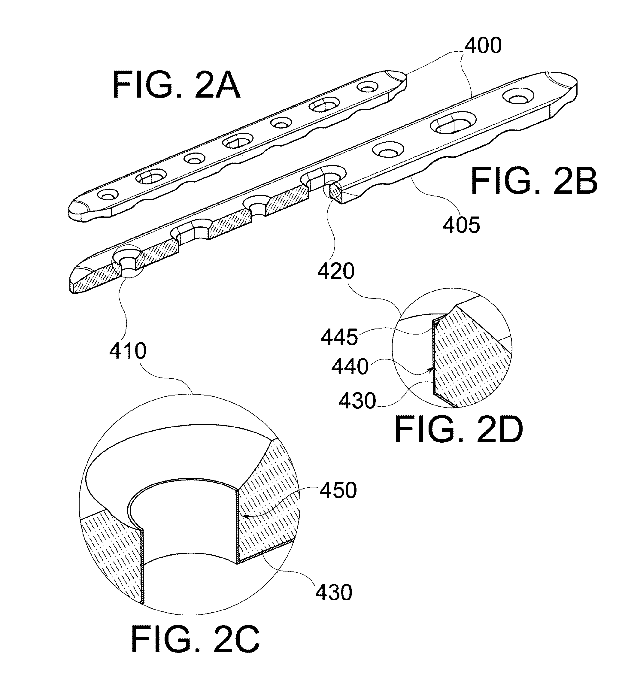
The present invention relates to bone implant devices made of fiber-reinforced polymer composite construction and to methods for manufacturing such devices. More specifically, the invention relates to the surface characteristics of such devices and to the use of a layer of reinforcement fiber-free PEEK to shield the body of the device from wearing contacts over at least one exterior facing surface region. The invention also includes the use of a restraining strip to hold the edge region of the layer in a recess of the body. The technical effects of the invention include improved wear resistance and reduced bone resorption, as well as improved osteoblast attachment and reduced inflammation.

Problems solved by technology

A rigid metal bone plate creates relatively high stresses in certain regions of the bone, with insufficient load transfer, resulting in stress shielding.
Both high stress and stress shielding can cause bone deterioration and resorption, leading to areas of bone weakness and loss of bone support for the implant.

Method used


Image

  • Composite implant coating
  • Composite implant coating
  • Composite implant coating

Examples


Embodiment Construction

[0093]The present invention, in some embodiments thereof, relates to composite material bone implant devices and to manufacturing methods for such devices. More particularly, but not exclusively, the invention in some embodiments relates to such devices and methods as applied to implant devices formed of fiber-reinforced polymer matrices. Still more particularly, the invention in some embodiments relates to the surface characteristics of such implant devices, such as may be conferred, for example, by a surface coating.

[0094]Overview

[0095]An aspect of some embodiments of the invention relates to a coating layer which shields a portion of a bone implant surface from wearing interactions with bone and / or with other bone implant component surfaces. In some embodiments of the invention, the coating layer comprises a polymer, for example PEEK. In some embodiments of the invention, the coating layer is of a metal foil, such as titanium.

[0096]According to some embodiments, other coating mat...


PUM

PropertyMeasurementUnit
sizeaaaaaaaaaa
sizeaaaaaaaaaa
thicknessaaaaaaaaaa

Abstract

A coating layer, for example PEEK or titanium foil, shields a bone implant surface from wearing interactions with surfaces of bone and / or other implants. The coating prevents shedding particles which are difficult to distinguish from evidence of potentially dangerous conditions, for example, microorganism contamination and / or degenerating tissue. Methods and structures for securing a coating layer are described. Other uses and implementations of coating layers are described.

Description

RELATED APPLICATION / S[0001]This application claims the benefit of priority under 35 USC §119(e) of U.S. Provisional Patent Application No. 61 / 724,983 filed Nov. 11, 2012, and of U.S. Provisional Patent Application No. 61 / 841,966 filed Jul. 2, 2013, the contents of which are incorporated herein by reference in their entirety.[0002]The present application is related to International Patent Application No. PCT / IB2010 / 050225 to Beyar, filed Jan. 18, 2010; to International Patent Application No. PCT / IB2011 / 052468 to Globerman, filed Jun. 7, 2011; and to U.S. Provisional Patent Applications Nos. 61 / 586,853, 61 / 617,067 and 61 / 641,900, all to Beyar, filed on Jan. 16, 2012, Mar. 29, 2012, and May 30, 2012, respectively.[0003]The contents of the above applications are all incorporated by reference as if fully set forth herein in their entirety.FIELD AND BACKGROUND OF THE INVENTION[0004]The present invention, in some embodiments thereof, relates to composite material bone implant devices and t...

Claims


Application Information

Patent Timeline
Patent Type & Authority Applications(United States)
IPC IPC(8): A61B17/80
CPCA61B17/8033A61B2017/00526A61B17/80A61B17/7059A61B17/72A61B17/866A61L31/082A61L31/10A61L31/126A61L31/18A61L2420/08A61L2430/02C08L71/12
Inventor BEYAR, MORDECHAYGLOBERMAN, ORENSHAVIT, RONEN
Owner CARBOFIX SPINE INC
Learn More