Methods and Systems for Controlling a Blood Pump

a technology of blood pump and control method, which is applied in the direction of heart stimulators, prostheses, therapy, etc., can solve the problems of heart failure that is too weak to pump enough blood to your body, advanced heart failure, and shortness of breath and fatigue of people with heart failure, so as to improve the duration of vad operation and sustain the effect of operation

Active Publication Date: 2015-10-15
TC1 LLC
View PDF7 Cites 41 Cited by
  • Summary
  • Abstract
  • Description
  • Claims
  • Application Information

AI Technical Summary

Benefits of technology

[0007]The present invention provides improved systems, methods, and devices which can advantageously sustain VAD operation during low power conditions. Improving the duration of VAD operation during low power has many advantages, such as patient safety, as discussed herein. For example, identifying a mode to conserve power and transitioning from a first operational mode (e.g., pulsatility mode) to a second operation mode (e.g., steady-state) to save on power reserves allows the VAD to continue to operate uninterrupted for longer durations of time while the patient safely secures alternative power sources or recharges existing power sources. Still further, the present invention finds applicability with both external power sources and fully implantable transcutaneous energy transfer systems.

Problems solved by technology

People with heart failure often have shortness of breath and fatigue.
Years of living with blocked arteries or high blood pressure can leave your heart too weak to pump enough blood to your body.
As symptoms worsen, advanced heart failure develops.

Method used


Image

  • Methods and Systems for Controlling a Blood Pump
  • Methods and Systems for Controlling a Blood Pump
  • Methods and Systems for Controlling a Blood Pump

Examples


Embodiment Construction

[0058]In the foregoing specification, the invention is described with reference to specific embodiments thereof, but those skilled in the art will recognize that the invention is not limited thereto. Various features and aspects of the above-described invention can be used individually or jointly. Further, the invention can be utilized in any number of environments and applications beyond those described herein without departing from the broader spirit and scope of the specification. The specification and drawings are, accordingly, to be regarded as illustrative rather than restrictive. It will be recognized that the terms “comprising,”“including,” and “having,” as used herein, are specifically intended to be read as open-ended terms of art.

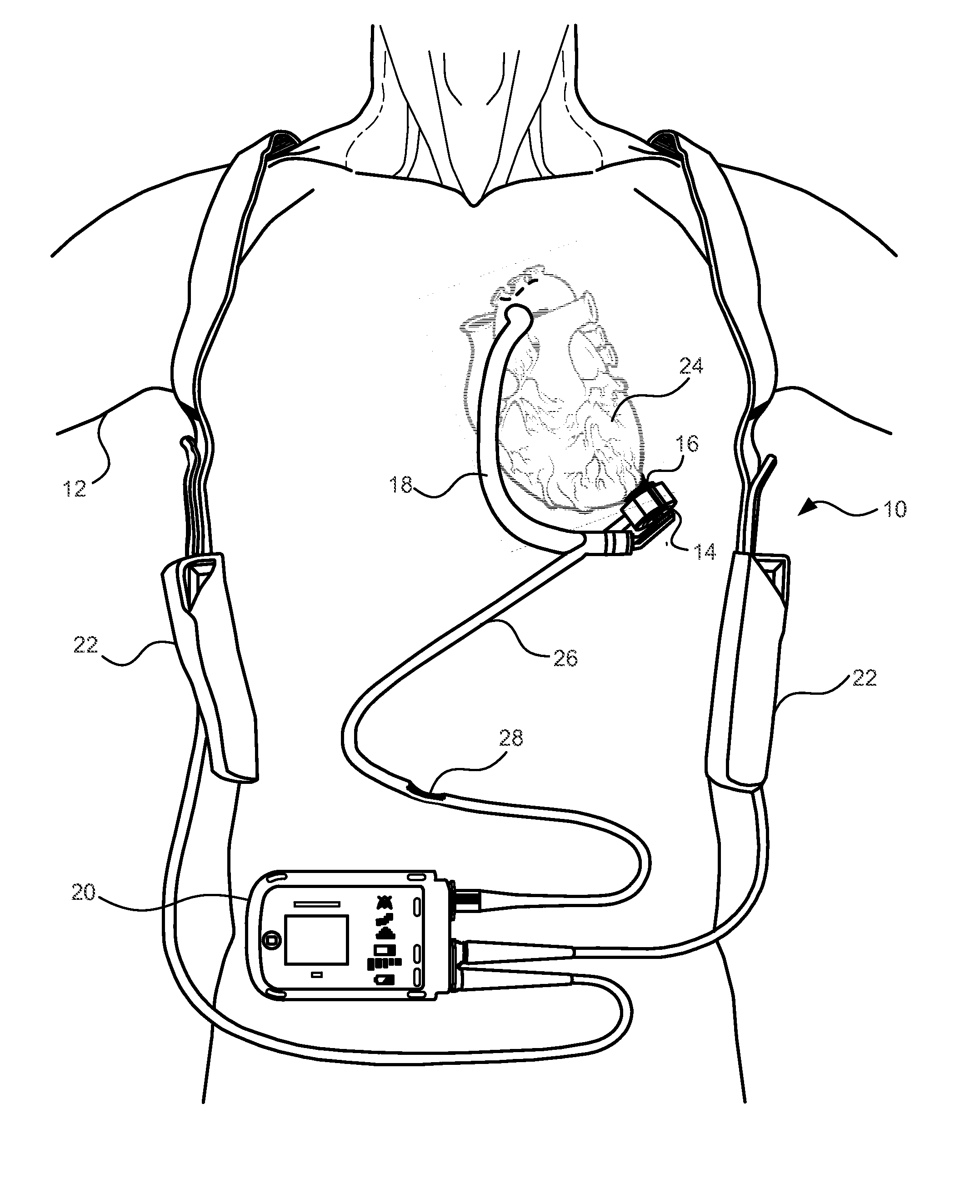
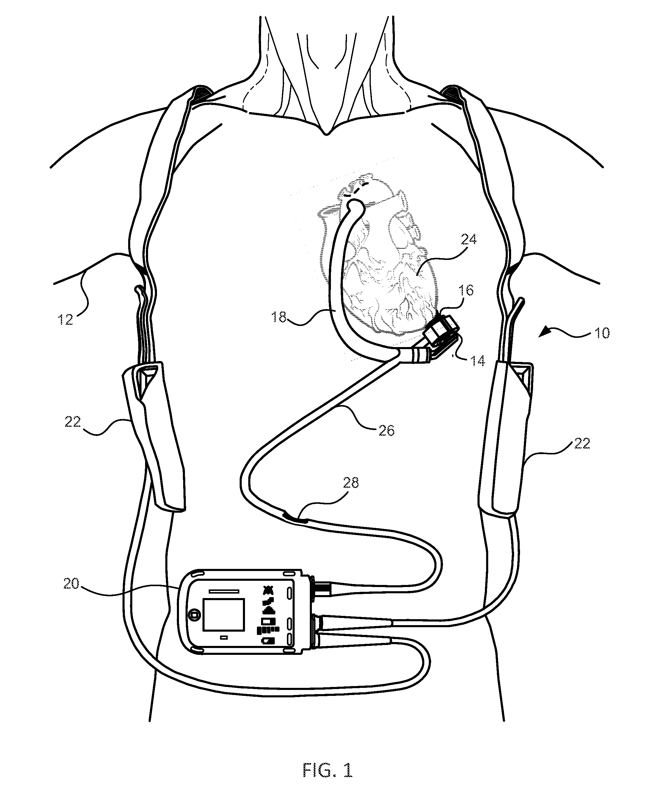
[0059]FIG. 1 is an illustration of a mechanical circulatory support system 10 implanted in a patient's body 12. The mechanical circulatory support system 10 comprises a implantable blood pump 14, ventricular cuff 16, outflow cannula 18, system co...


PUM


Abstract

The present invention generally relates to ventricular assist device power monitoring and conservation. In some embodiments, a pump controller may transition the pump to operate in a power-saving operational mode when a power source and/or a power source condition indicate a need to conserve power. In some embodiments, when the power source is an emergency battery and when the emergency battery has powered the pump for an extended period of time, the controller may signal the pump to operate in the power saving-operational mode. In some embodiments, when a low power hazard condition is triggered by signals from one or more external power sources, the controller may signal the pump to transition to the power-saving operational mode if the condition lasts for an extended period of time. In some embodiments, the controller may trigger the power-saving mode when the emergency backup battery is below a voltage threshold.

Description

CROSS REFERENCE TO RELATED APPLICATION DATA[0001]The present application claims the benefit under 35 USC §119(e) of U.S. Provisional Appln. No. 61 / 979,840 filed Apr. 15, 2014. The full disclosure which is incorporated herein by reference in its entirety for all purposes.FIELD OF THE INVENTION[0002]This description relates to generating an artificial pulse, and more specifically to methods and systems for power saving and disabling pulsatility.BACKGROUND OF THE INVENTION[0003]This application relates generally to mechanical circulatory support systems, and more specifically relates to power management systems and methods for an implantable blood pump.[0004]Ventricular assist devices, known as VADs, are implantable blood pumps used for both short-term (i.e., days, months) and long-term applications (i.e., years or a lifetime) where a patient's heart is incapable of providing adequate circulation, commonly referred to as heart failure or congestive heart failure. According to the Ameri...

Claims


Application Information

Patent Timeline
Patent Type & Authority Applications(United States)
IPC IPC(8): A61M1/10A61M1/12
CPCA61M1/1086A61M1/127A61M1/1005A61M1/122A61M2205/8262A61M2205/14A61M2205/3334A61M2205/50A61M2205/8212A61M2205/8243A61M60/422A61M60/148A61M60/81A61M60/232A61M60/857A61M60/237A61M60/178A61M60/569A61M60/873A61M60/876
Inventor BOURQUE, KEVINKIMBALL, BRIANDAGUE, CHARLES P.
Owner TC1 LLC
Why Eureka
Try Eureka