Method of manufacturing a compressed gas cylinder

a technology of compressed gas and manufacturing method, which is applied in the direction of packaging foodstuffs, packaged goods type, other domestic articles, etc., can solve the problems of mechanical inefficiency, low production efficiency, and high labor demand of process, and achieve less variation in the cured part, less volatile gas compounds, and less volatile gas compounds.

Inactive Publication Date: 2015-10-15
FIVES MACHINING SYST
View PDF8 Cites 18 Cited by
  • Summary
  • Abstract
  • Description
  • Claims
  • Application Information

AI Technical Summary

Benefits of technology

[0012]A liner is wrapped with pre-impregnated fiber tow using a conventional filament winding process. The prepreg tow provides a more controlled resin content and less variation in the cured part than other processes, and provides a cleaner process than a wet process, with little or no emission of volatile gas compounds. The resin may contain a nano material that increases the strength of the resulting c

Problems solved by technology

Type 1 cylinders are all metal and are mechanically inefficient since circumferential stress loads in a pressurized gas cylinder are approximately double the axial stress loads.
Although these developments have reduced the winding time, the labor demand of the process is still relatively high.
The main reasons are the problems associated with the use of resin baths for fiber impregnation and the relatively low winding speeds associated with fiber impregnation that is coupled with

Method used


Image

  • Method of manufacturing a compressed gas cylinder
  • Method of manufacturing a compressed gas cylinder
  • Method of manufacturing a compressed gas cylinder

Examples


Embodiment Construction

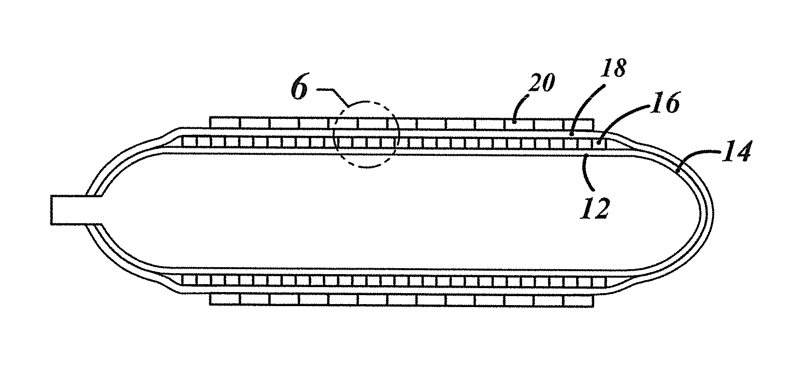
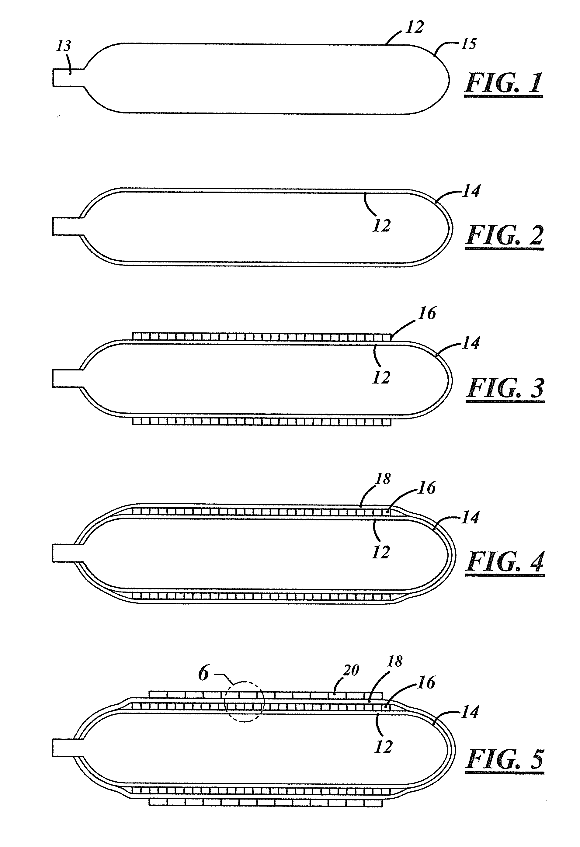
[0024]FIG. 1 is a side view of a cylinder liner 12 prior to being wound with reinforcing fiber. The cylinder 12 is shown with a connector neck 13 at one end and a domed termination 15 at the other end, but the cylinder may be formed with connector necks 13 at both ends if desired. The cylinder may comprise aluminum, steel, or any other metal that can be formed into a thin wall container. The cylinder may also comprise plastic or other similar non-metallic material.

[0025]FIG. 2 is a side view of the cylinder 12 after being wound longitudinally, end to end with prepreg fiber 14. The use of fiber 14 with resin coated onto the fiber, or prepreg fiber, eliminates the need for a costly resin transfer molding process that is required if the cylinder is wound with dry or un-impregnated fiber. To comply with US Department of Transportation requirements, if the cylinder 12 is metal, a galvanic corrosion protection layer is required between the metal and the outer reinforcing layers. For this ...


PUM

PropertyMeasurementUnit
Pressureaaaaaaaaaa
Shrinkageaaaaaaaaaa
Strengthaaaaaaaaaa

Abstract

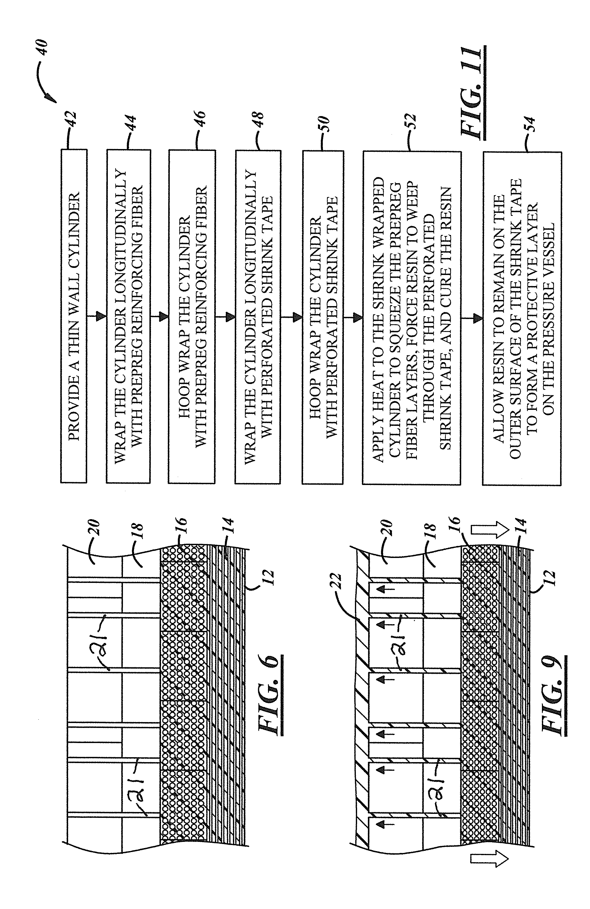
A method of forming a reinforced pressure vessel includes the steps of providing a thin wall cylinder, wrapping the cylinder with at least one layer of prepreg reinforcing fiber, wrapping the cylinder with at least one layer of perforated shrink tape, applying heat to the shrink wrapped cylinder to squeeze the at least one prepreg fiber layer to force resin to weep through the perforated shrink tape and cure the resin, and allowing the resin to remain on the outer surface of the shrink tape to form a protective layer on the pressure vessel.

Description

[0001]This application claims priority of U.S. provisional application Ser. No. 61 / 614,207 filed Mar. 22, 2012 and international application PCT / US2013 / 030725 filed Mar. 13, 2013.FIELD[0002]A method of manufacturing a pressure vessel for containing a compressed gas is disclosed in which a thin wall cylinder is wrapped with resin impregnated reinforcing fiber and shrink wrap polymeric tape prior to being cured to eliminate voids in the cured composite and to form a protective layer on the vessel.BACKGROUND[0003]Compressed natural gas (CNG) and pressurized hydrogen are finding increasing application as an alternative fuel for internal combustion engines. As a result, there is a need to have relatively light weight high strength pressure vessels to contain the pressurized gas. The mechanical requirements for such pressure vessels include a relatively high burst strength on the order of 10,000 psi.[0004]There are four general categories of pressure vessels that are used to store compres...

Claims


Application Information

Patent Timeline
IPC IPC(8): F17C1/04B32B37/14
CPCF17C1/04B32B37/142B32B37/144B32B2305/08B32B2439/40B32B2307/50B32B2313/04B32B2323/04B32B2367/00B32B2307/736B29L2031/7156B29C53/602B29C61/006B29C63/08B29C70/347B29C70/86B29C70/086
Inventor CURLESS, RICHARD A.BROOKSTEIN, DAVID S.KAPPESSER, RANDALL A.ALLMAN, DANIEL
Owner FIVES MACHINING SYST
Why Eureka
Try Eureka