Fringe Reduction in Laser Spectroscopy

a laser spectroscopy and fringe reduction technology, applied in the field of optics, can solve the problems of limiting the sensitivity of laser spectroscopy measurement of trace gas concentration, affecting the accuracy of laser spectroscopy, so as to reduce the speed of amplitude variation or fringe noise

a laser spectroscopy and fringe reduction technology, applied in the field of optics, can solve the problems of limiting the sensitivity of laser spectroscopy measurement of trace gas concentration, affecting the accuracy of laser spectroscopy, so as to reduce the speed of amplitude variation or fringe noise

US20150292944A1Inactive Publication Date: 2015-10-15NEC LAB AMERICA

Image

  • Fringe Reduction in Laser Spectroscopy
  • Fringe Reduction in Laser Spectroscopy
  • Fringe Reduction in Laser Spectroscopy

Examples


Embodiment Construction

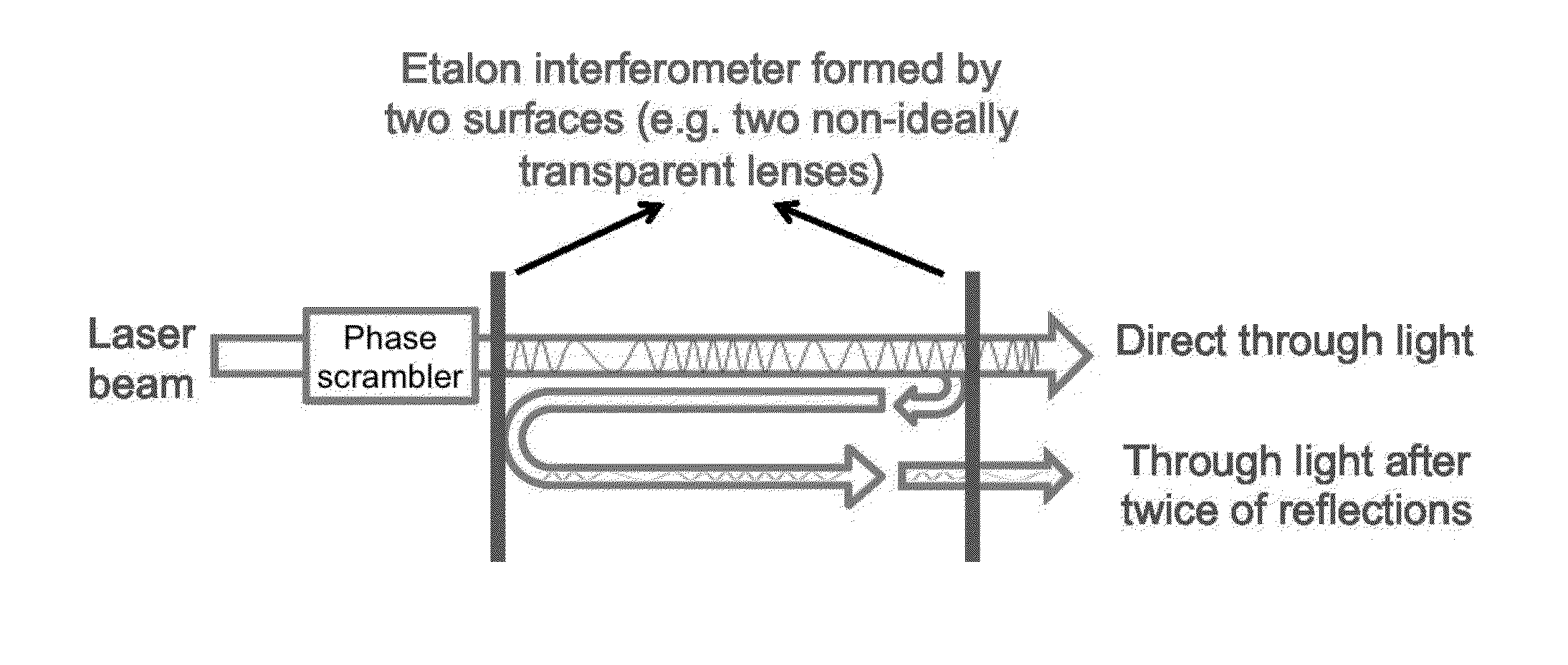
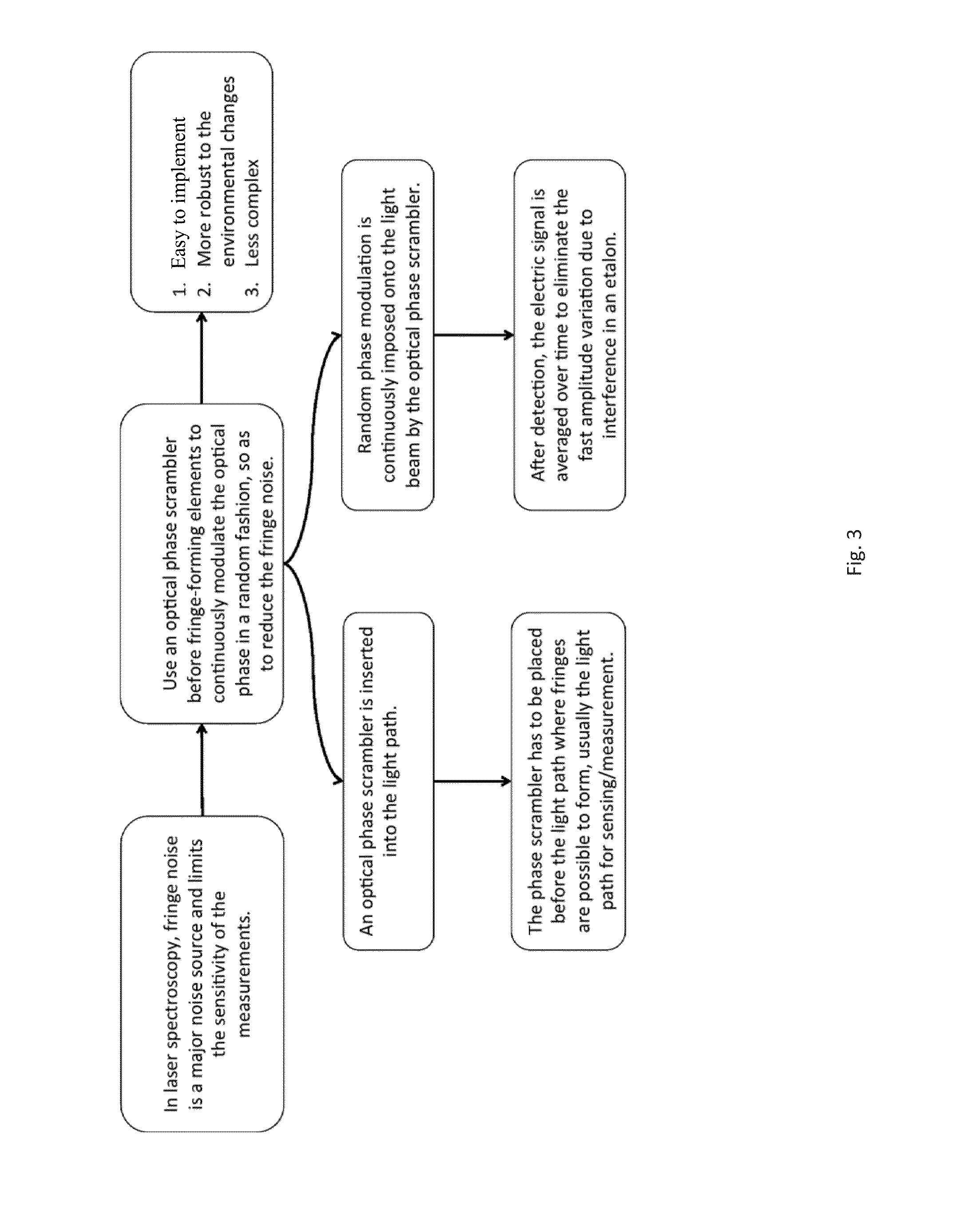
[0014]The invention provides an optical phase scrambler that is placed next to a laser source to randomly modulate the optical phase. Since the optical phase is continuously changing in a random fashion, at the output of an etalon interferometer formed in the optical path, the two or more components in the interference always have certain time delay between each other, resulting in a random phase different between each other. Therefore, after interference, the fringe amplitude varies randomly as well. Then at the receiver side, the fringe noise is greatly reduced after it is averaged over time.

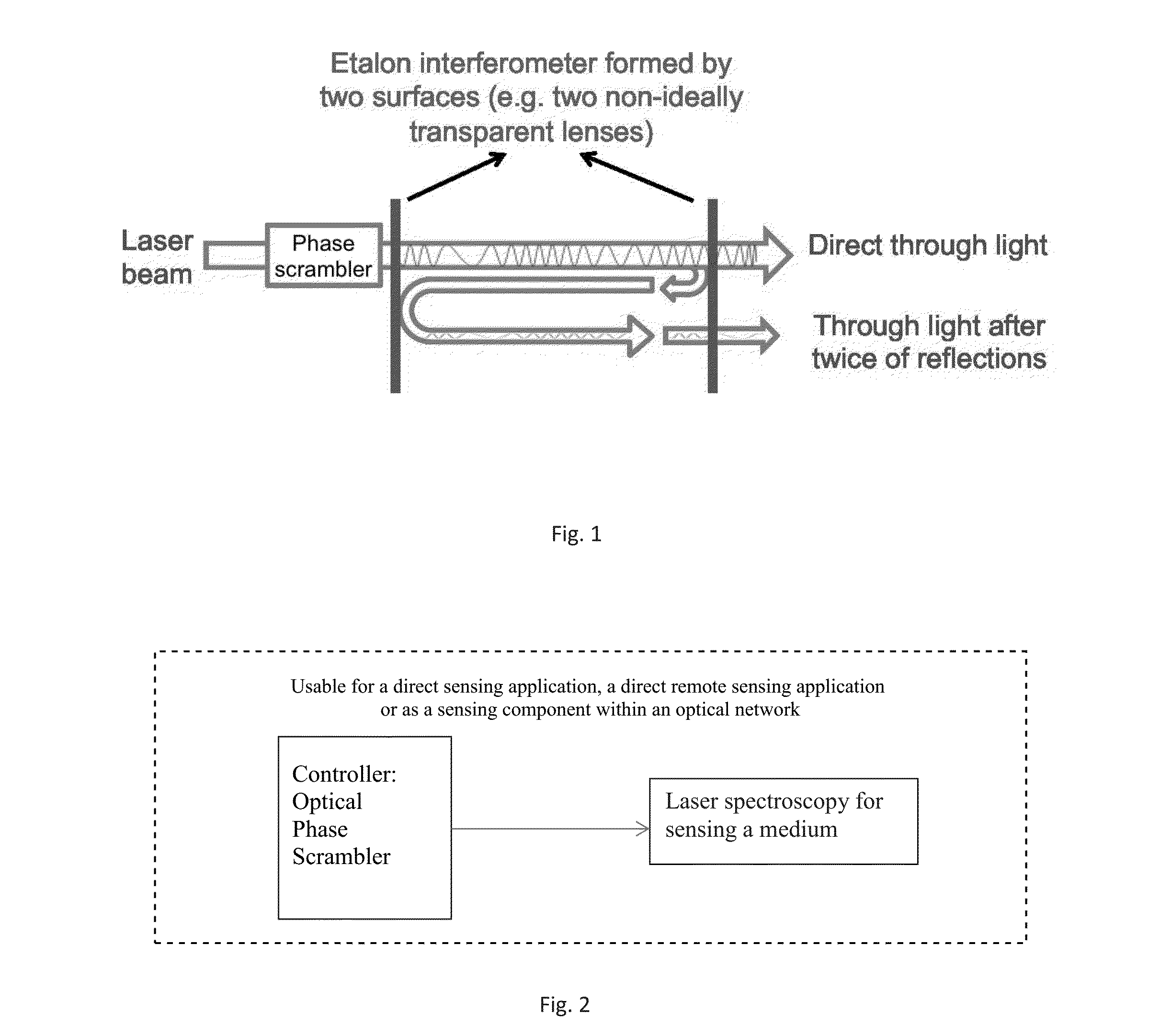
[0015]FIG. 1 shows application of the inventive fringe reduction in a laser spectroscopy situation.

[0016]A phase scrambler is placed between the laser beam light source and Etalon interferometer. The Etalon interferometer is formed by two surfaces, e.g., two non-ideally transparent lenses. The interferometer produces a direct light output and a light output after two reflections inside the Eta...


PUM


Abstract

An optical phase scrambler is coupled to a laser source to randomly modulate the optical phase. Since the optical phase is continuously changing in a random fashion, at the output of an etalon interferometer formed in the optical path, the two or more components in the interference always have certain time delay between each other, resulting in a random phase different between each other. Therefore, after interference, the fringe amplitude varies randomly as well. Then at the receiver side, the fringe noise is greatly reduced after averaging over time.

Description

RELATED APPLICATION INFORMATION[0001]This application claims priority to provisional application No. 61 / 978,069, filed Apr. 10, 2014, entitled “Fringe reduction method in linear spectroscopy”, and claims priority to provisional application 61 / 978,044, entitled “Optical Fiber-Based Remote Gas Leakage Monitoring with Sensor Identifier”, filed Apr. 10, 2014, the contents thereof are incorporated herein by reference.BACKGROUND OF THE INVENTION[0002]The present invention relates generally to optics, and more particularly, to fringe reduction in laser spectroscopy.[0003]In laser spectroscopy for trace gas sensing, the effect of etalon fringes on laser spectra is a major noise source, which consists of periodic ripple in the transmitted laser power across the spectra. This fringe noise usually limits the sensitivity of a laser spectroscopy measurement of a trace gas concentration.[0004]Minimization of interference fringe effects has been carried out by several approaches. Additional wavele...

Claims


Application Information

Patent Timeline
15 Oct 2015
Publication
US20150292944A1
IPC
G01J3/02; G01J3/45
CPC
G01J3/0297; G01J3/0205; G01J3/45; G01J3/26; G01J3/28
Inventors
TIAN, YUE; WANG, TING