
Unit and method for optical non-contact oil detection

a non-contact oil and unit technology, applied in the field of optical non-contact oil detection, can solve the problems of false alarms, complex systems, and high cost of continuous local on-site monitoring, and achieve the effect of ensuring exploitation

Active Publication Date: 2015-10-15
NEMOR TECH OU
View PDF9 Cites 16 Cited by
  • Summary
  • Abstract
  • Description
  • Claims
  • Application Information

AI Technical Summary

Benefits of technology

The invention is a device that has a housing filled with neutral gas at overpressure. This makes the device waterproof and hermetic, which adds an extra layer of safety and protection against humidity. This helps to protect the device's optical and electronic components.

Problems solved by technology

Being very effective as mobile units, such systems are often too complex and expensive for continuous local on-site monitoring.
Such an assumption does not work in case of oil products having the fluorescence in too distinguishing spectral ranges.
As the method does not specify the data analysis, one can assume registering the anomalous signals caused by other than oil light reflecting materials on water surface, also possibly producing false alarms.
1) Using powerful Xe-lamp as a light source makes the sensor bulky and power consuming, causing principal limitations of the detection distance due to significant beam divergence (light beam has a shape of cone with apex angle 13-15 degrees), increase of the distance will require unreasonable increase of the power consumption.
It limits its installation requirements and hampers operation in scanning mode when the inclination angle is varied.
4) The detection limited to the spectral range 320-400 nm does not allow detection of oil products fluorescing at longer wavelengths (FIG. 2).

Method used


Image

  • Unit and method for optical non-contact oil detection
  • Unit and method for optical non-contact oil detection
  • Unit and method for optical non-contact oil detection

Examples


Embodiment Construction

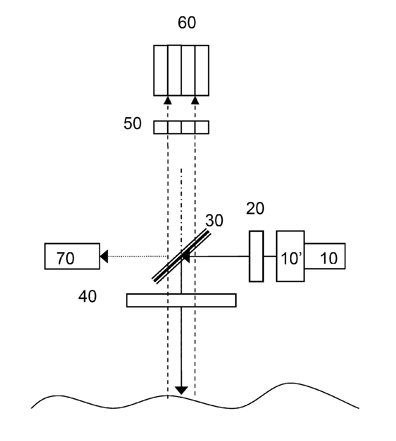
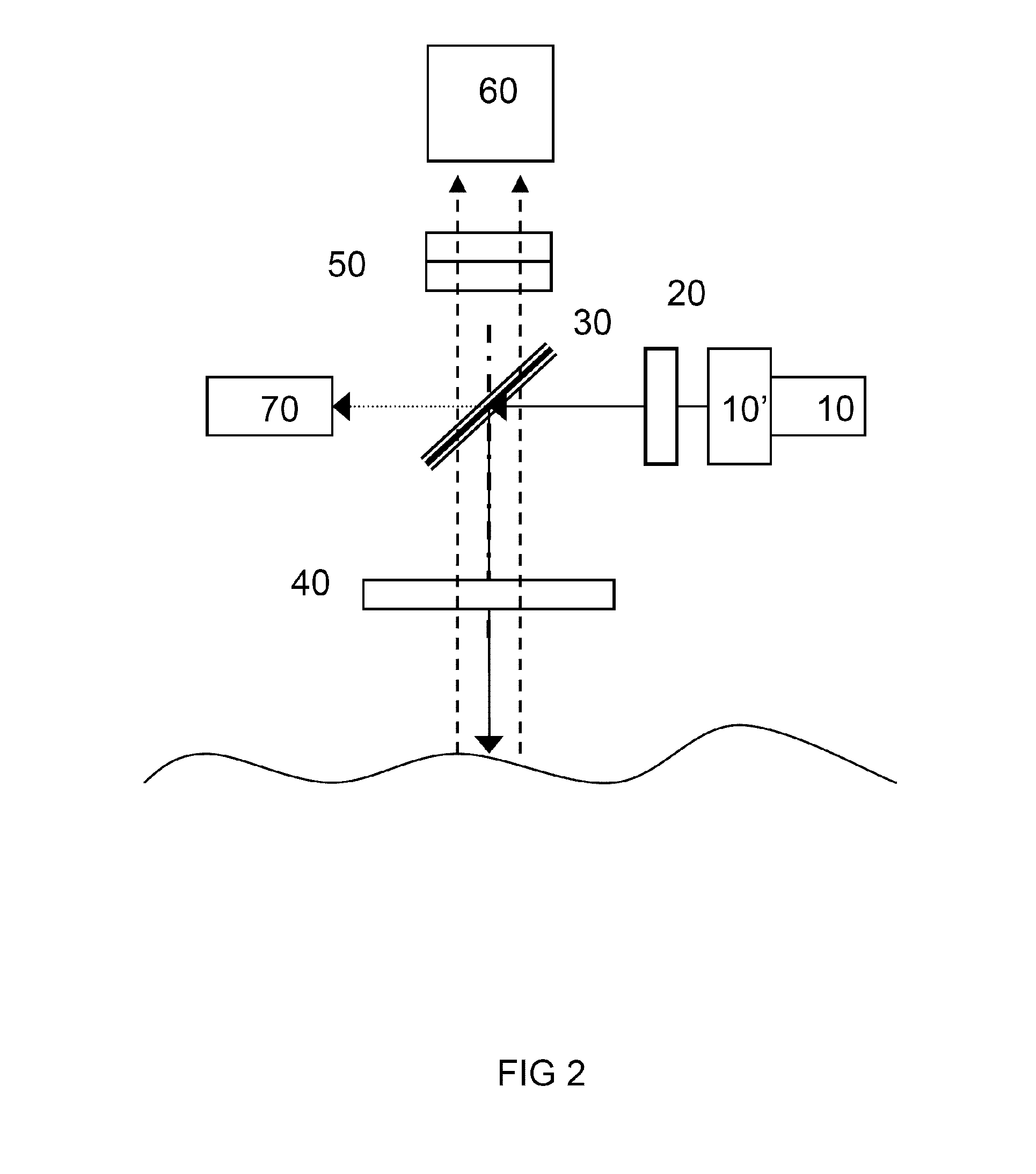
[0039]The present invention provides the unit and the method for reliable detection of oil products which may appear in the controlled area and they will be described hereinafter in a more detail.

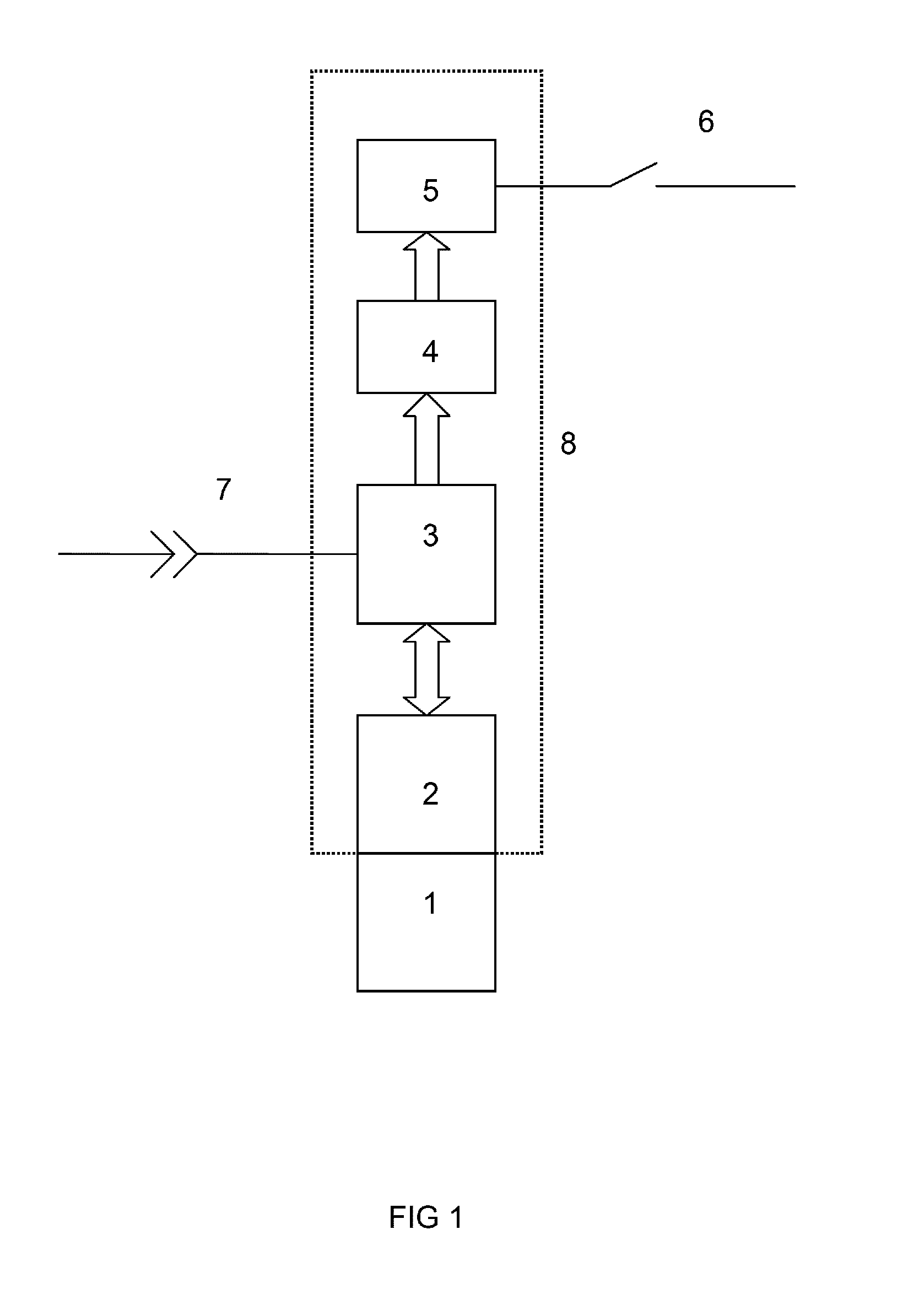
[0040]In FIG. 1 is shown electro-mechanical block-scheme of the unit. The unit includes opto-electronic unit 2 (hereinafter—“sensor”) that is provided with a protective snoot 1 and connected to electronic compartment 3 (FIG. 1). Sensor is followed by microprocessor controller 4 with embedded software for carrying out necessary analyses of reflected signals received by sensor. The controller 4 is connected to communication means 5 for transmitting an alarm signal through external communication line 6 in case of oil pollution. Considered communication means may be any contact or wireless communication line supported by microcontroller, namely LAN, RS485, Radio Link, Wi-Fi, GSM, Bluetooth, or any other custom solution. The waterproof and hermetic housing can be also filled with neutral gas at ...


PUM

PropertyMeasurementUnit
emission wavelengthaaaaaaaaaa

Abstract

The invention relates to a unit and method for detection of presence of oil on the water surface or in the water column. Unit comprises a sensor, whereby the sensor is connected to electronic compartment followed by microprocessor controller with embedded software for carrying out necessary analyses of reflected signals received by the sensor. The microprocessor controller is connected to communication means for transmitting an alarm signal through external communication line in case of oil pollution. All elements mentioned above are supplied by external power supply and are accommodated into waterproof housing. The sensor comprises the probe light source formed by a pulsed UV LED, collimating optics and narrow band optical filter, at least one dichroic mirror, a projection-receiving lens, at least one optical filter, at least one photodetector and a reference photodetector.

Description

TECHNICAL FIELD[0001]The present invention relates to a unit and method for detection of presence of oil on the water surface or in the water column.BACKGROUND ART[0002]In-time detection of water pollution by oil remains a relevant task to prevent environmental damage due to the spill and pollution spreading and loss of the product caused by the leak incidents. Among the variety of the techniques used for the task, the most demanded are the ones capable of operating in real-time, unattended, and with minimal maintenance.[0003]The Light Induced Fluorescence (LIF) is well known high sensitive method used for detection of oil in water. It is referred to as an active method due to the use of controlled light source. The selectivity of oil detection with this method is provided due to the fact that at properly selected spectrum of the inducing light the poly-aromatic hydrocarbons (PAH) of oil products produce fluorescence with specific spectral profile. This profile differs from spectral...

Claims


Application Information

Patent Timeline
Patent Type & Authority Applications(United States)
IPC IPC(8): G01N21/94G01N21/64
CPCG01N21/94G01N21/64G01N2201/061G01N2021/6421G01N2021/945G01N2201/021G01N2201/062G01N2201/0625G01N2201/0696
Inventor BABICHENKO, SERGEY
Owner NEMOR TECH OU
Learn More