Inverter device

a technology of inverter and capacitor, which is applied in the direction of capacitor propulsion, battery/fuel cell control arrangement, instruments, etc., can solve the problems of long time-consuming and laborious, and limited current value of warm-up control of capacitors, etc., and achieve internal resistance increase, internal resistance increase of battery, and undesirable increase of voltage drop amoun

Inactive Publication Date: 2015-10-15
TOYOTA IND CORP
View PDF5 Cites 11 Cited by
  • Summary
  • Abstract
  • Description
  • Claims
  • Application Information

AI Technical Summary

Benefits of technology

[0003]To promptly increase the capacitor temperature, a great current may be supplied during the warm-up control. However, if a great current is supplied to the inverter device under a low-temperature environment as the warm-up control, the voltage drop amount is undesirably increased since the internal resistance of the capacitor is increased. If the voltage drop amount is great, the system becomes unstable, and the microcomputer of the inverter device may be reset. The internal resistance of a battery changes depending on the charge state. Furthermore, in a case in which the battery is used in a low charge state, the internal resistance of the battery is increased by an amount corresponding to the decrease in the charge state in addition to the internal resistance of a case in which the battery is used in a fully charged state. Conventionally, the warm-up control is performed with a current value that depends on the assumption that the battery charge state is the lowest. When such a control is performed, the current value of the warm-up control is limited even if the battery charge state has not lowered, and the warm-up control of the capacitor takes a long time.

Problems solved by technology

However, if a great current is supplied to the inverter device under a low-temperature environment as the warm-up control, the voltage drop amount is undesirably increased since the internal resistance of the capacitor is increased.
If the voltage drop amount is great, the system becomes unstable, and the microcomputer of the inverter device may be reset.
When such a control is performed, the current value of the warm-up control is limited even if the battery charge state has not lowered, and the warm-up control of the capacitor takes a long time.

Method used


Image

  • Inverter device
  • Inverter device
  • Inverter device

Examples


first embodiment

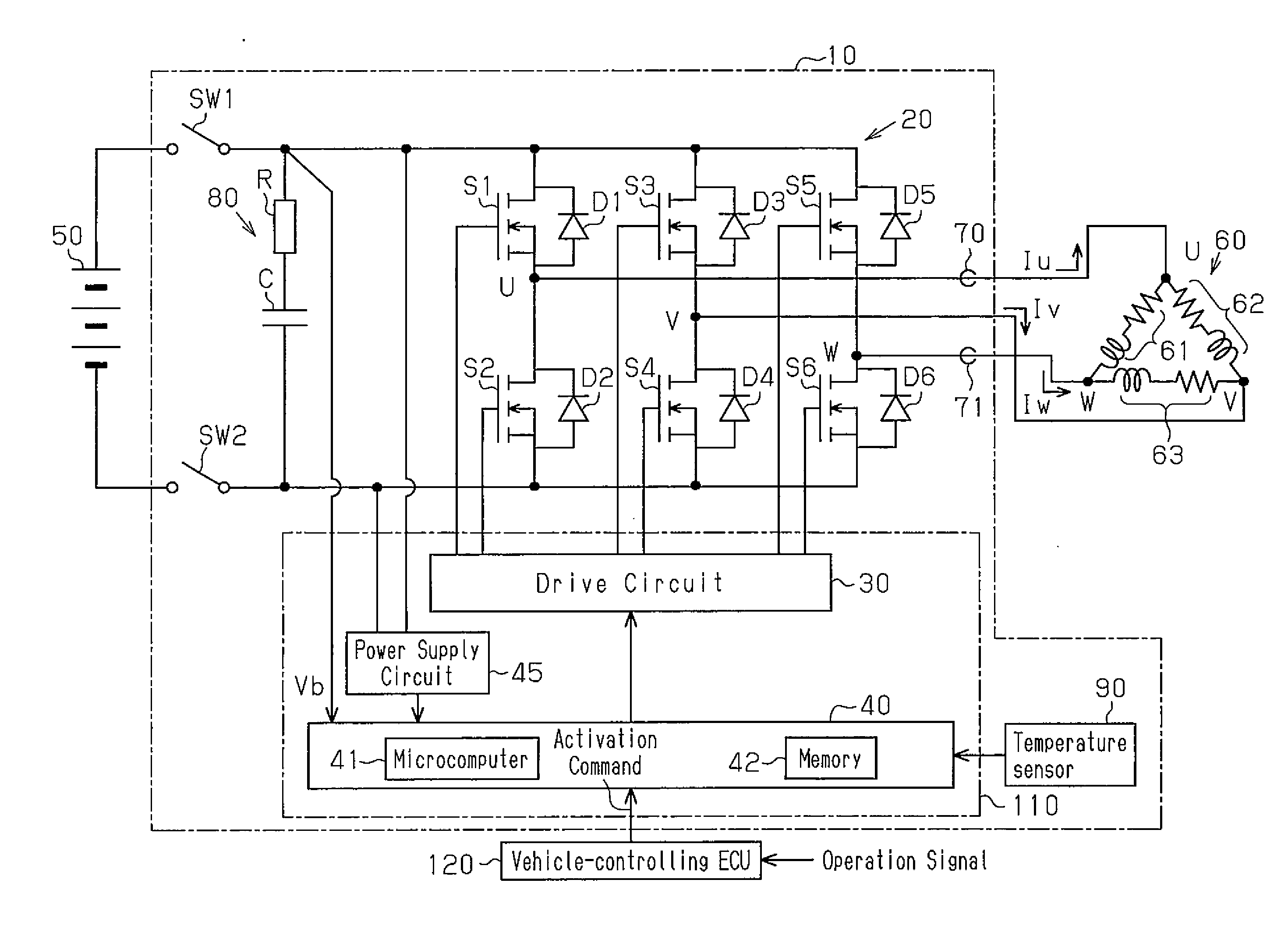
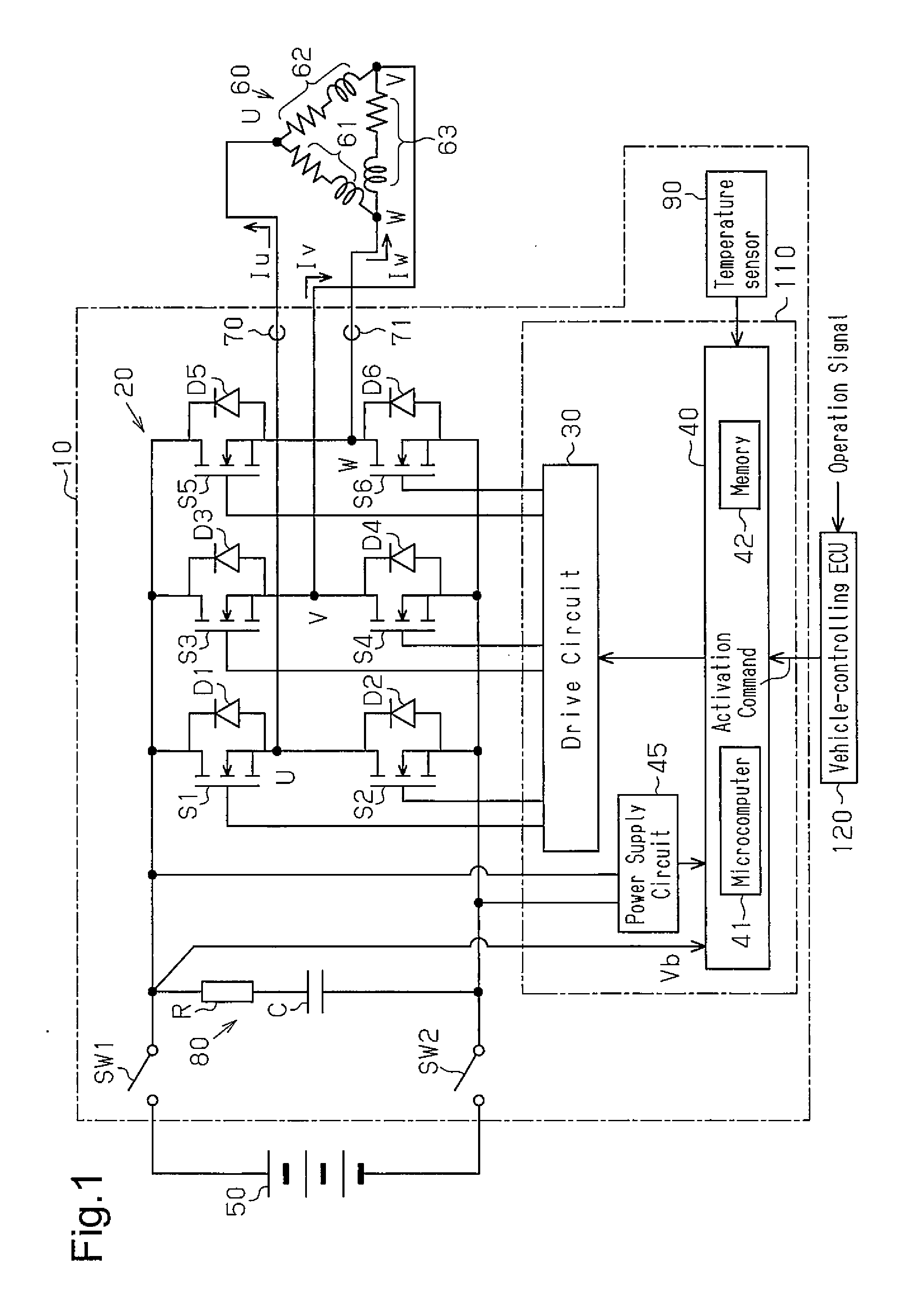
[0018]An inverter device according to one embodiment of the present invention will now be described with reference to the drawings. The inverter device is mounted on a forklift and activates a driving electric motor and a cargo handling electric motor of the forklift. The forklift is a battery-operated forklift. The forklift is driven by a vehicle driving electric motor and performs cargo handling with a cargo handling electric motor. That is, when an operator operates an accelerator pedal in a state in which the key is turned on, the driving electric motor is activated to drive the forklift forward or rearward. When the operator manipulates the lift lever, the cargo handling electric motor is activated to lift or lower the fork to handle a cargo. Such a forklift may be used in a cold storage in which the ambient temperature is less than or equal to −40° C.

[0019]As shown in FIG. 1, an inverter device (three-phase inverter) 10 includes an inverter circuit 20, a drive circuit 30, and ...

second embodiment

[0052]A second embodiment will now be described. The differences from the first embodiment will be mainly discussed.

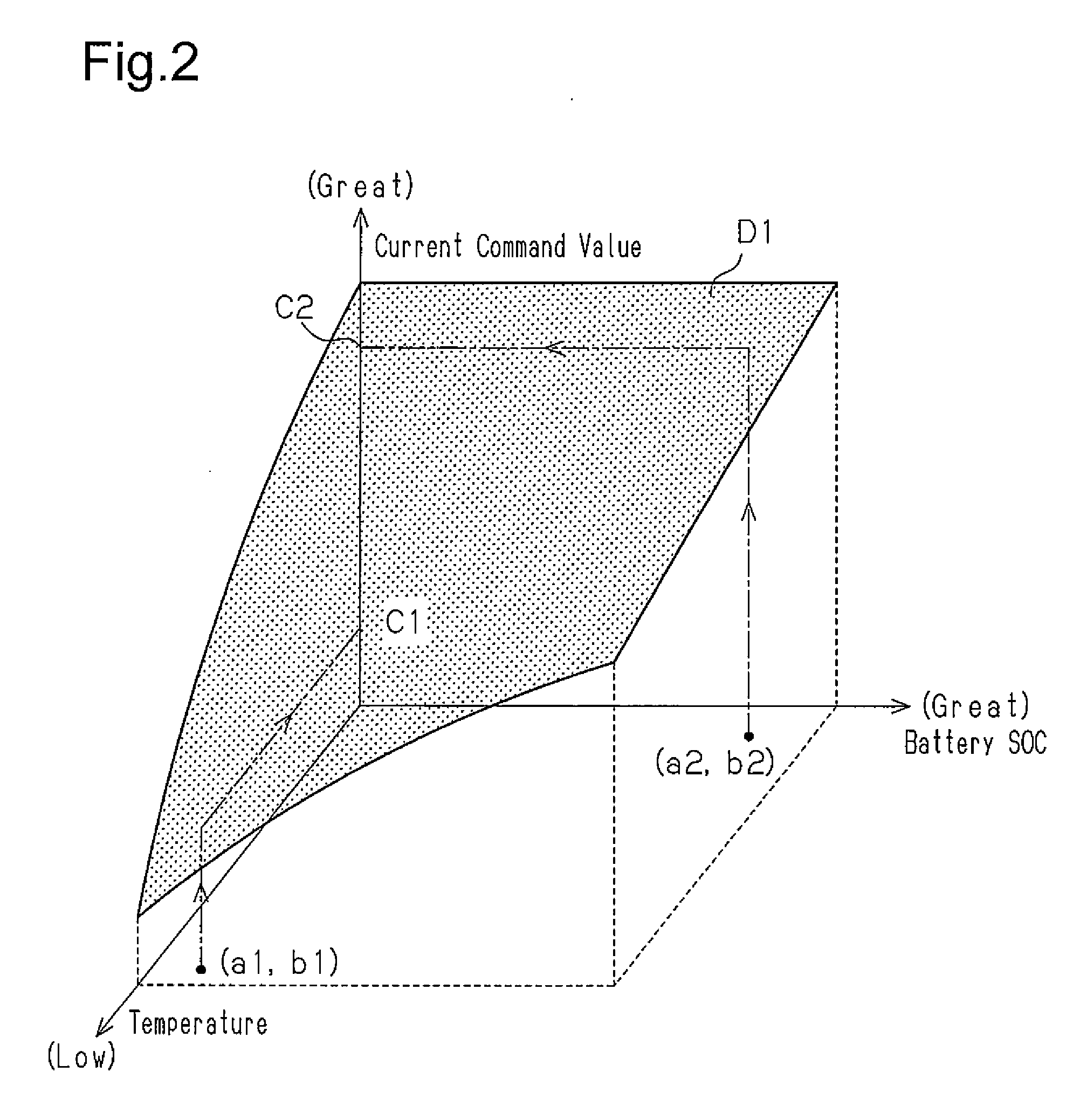
[0053]In general, the internal resistance of the capacitor and the battery is increased at low temperatures. Thus, during the warm-up control, the current command value for performing the warm-up control is determined such that the dropped voltage does not fall below a certain value factoring in the battery state of charge and the system temperature.

[0054]In the first embodiment, since the current command map shown in FIG. 2 is prepared in advance, the battery (rechargeable battery) is assumed to be the one that has the greatest internal resistance and the degree of deterioration among the various types. Thus, if the internal resistance of the battery (rechargeable battery) is small, the current value is reduced although the battery has a current supplying capability. From the perspective of users, the warm-up control is preferably promptly completed for full-power ope...

third embodiment

[0063]A third embodiment will now be described. The differences from the second embodiment will be mainly discussed.

[0064]The second embodiment includes the learning function in which the current command value corresponding to the temperature and the battery SOC in the current command map is updated based on the battery voltage during the warm-up control. The current command value when performing the warm-up control is determined based on the previously learned result. At this time, if the warm-up control is not frequently performed, that is, if the time period from when the previous warm-up control is performed to when the present warm-up control is performed is long, deterioration of the battery may have progressed. In this case, depending on the current command value, the voltage drop amount may be greater than expected and may undesirably fall below the minimum voltage required for system operation.

[0065]The present embodiment determines the optimal warm-up control current comma...


PUM


Abstract

An inverter device includes an inverter circuit, which has switching elements in a bridge connection, a capacitor, which is connected in parallel to the input side of the inverter circuit, a temperature detector, which detects the temperature of the capacitor, a battery charge information acquisition section, which acquires charge information related to a battery connected to the input side of the inverter circuit, and a warm-up controller. When the temperature of the capacitor detected by the temperature detector is lower than a prescribed temperature, the warm-up controller determines a warm-up current based on the battery charge information acquired by the battery charge information acquisition section and the temperature of the capacitor detected by the temperature detector, and controls the switching elements of the inverter circuit to supply the warm-up current to the coil of an electric motor connected to the output side of the inverter circuit.

Description

FIELD OF THE INVENTION[0001]The present invention relates to an inverter device.BACKGROUND OF THE INVENTION[0002]Patent Document 1 discloses a battery control system that properly controls a voltage drop of a battery at starting of a device under a low-temperature environment. Specifically, the system gradually increases a current flowing from the battery to a load (various components forming the device) while monitoring the voltage drop when the temperature of the device at starting is lower than a specific temperature. Inverter devices that drive a motor include a capacitor as a component. The internal resistance of the capacitor increases under a low-temperature environment. Thus, if a great input is applied to such an inverter device from the motor during, for example, regenerating operation, an internal voltage is increased, and switching elements, which are components of the inverter device, may possibly be destroyed. To avoid such a situation, the temperature of the capacitor...

Claims


Application Information

Patent Timeline
Patent Type & Authority Applications(United States)
IPC IPC(8): H02M7/5387G01R31/36
CPCH02M7/53871G01R31/3675G01R31/362H02P27/06B60L15/007B60L2210/30B60L2210/42B60L2240/525B60L2240/526B60L2240/529B60L2240/545B60L2240/547B60L2240/549H02M1/32H02M7/5387H02M7/53873H02P29/60H02P29/68H02P29/62H02P29/64B60L50/40B60L58/12B60L58/24B60L58/27Y02T10/64Y02T10/70Y02T10/72H02M1/327G01R31/374G01R31/3835B60L3/00
Inventor YAMAGAMI, TOMOHIRO
Owner TOYOTA IND CORP
Why Eureka
Try Eureka