
Dry anaerobic composting facility

a composting facility and anaerobic technology, applied in the field of dry anaerobic composting facilities, can solve the problems of low economic efficiency, difficulty in securing land, and complaints of nearby residents, and achieve the effect of efficient use of ground space and minimal energy loss

Inactive Publication Date: 2015-10-22
RESOURCIFICATION RES CENT FOR CROP ANIMAL FARMING
View PDF7 Cites 16 Cited by
  • Summary
  • Abstract
  • Description
  • Claims
  • Application Information

AI Technical Summary

Benefits of technology

The present invention provides a dry anaerobic composting facility that converts organic waste into a low-molecular weight compound through hydrolysis and acid fermentation, using a pre-treatment unit connected to a dry anaerobic fermentation unit. The facility produces high-quality compost and energy through self-generation using biogas produced during the fermentation process. Additionally, the facility minimizes energy loss and efficiently uses ground space, solving the problems of environmental pollution and unpleasant facilities.

Problems solved by technology

A common anaerobic treatment method which is the most generally used all over the world uses no composting facility, thus causing complaints from nearby residents due to unpleasant odor generated during decomposition of organic substances.
However, this anaerobic treatment method disadvantageously has a difficulty in securing land, in particular, in Korea, due to being mounted on the ground, and has low economic efficiency because heat loss caused by conduction and convection by low temperature and wind in winter may require supply of more auxiliary heat.
In addition, the conventional anaerobic treatment method includes supply of air to facilitate biodegradation of organic substances, thus causing deterioration in nitrogen component due to nitrification and having a problem associated with compost qualities.

Method used


Image

  • Dry anaerobic composting facility
  • Dry anaerobic composting facility
  • Dry anaerobic composting facility

Examples


Embodiment Construction

[0034]Hereinafter, a dry anaerobic composting facility according to the present invention will be described in detail with reference to the annexed drawings:

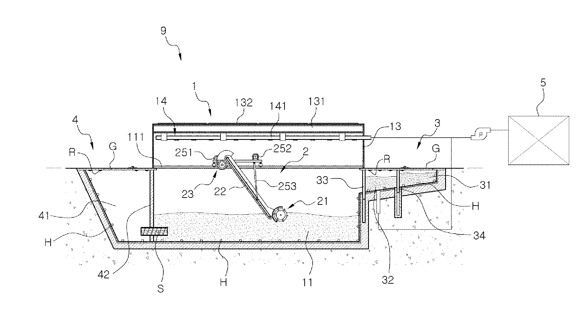
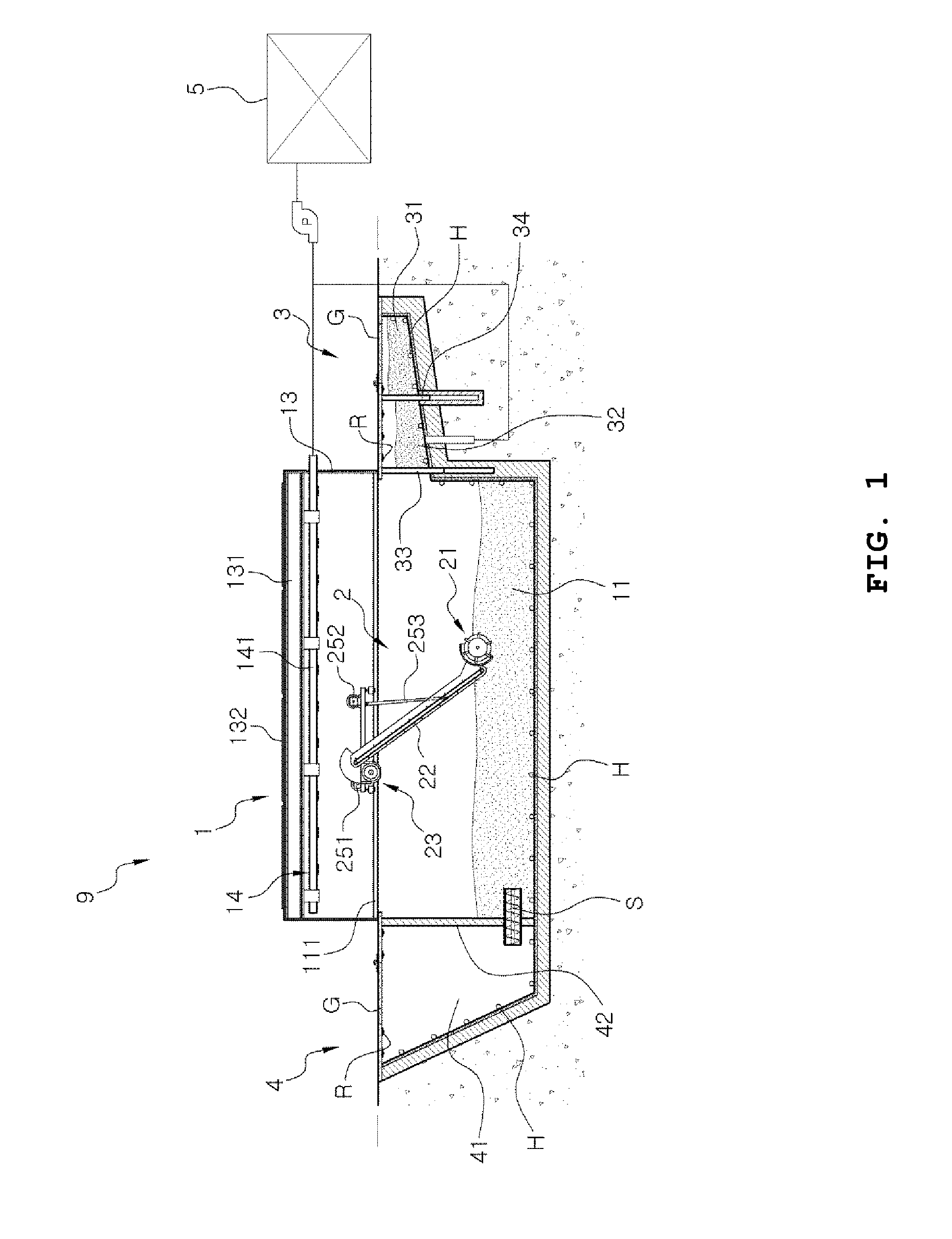
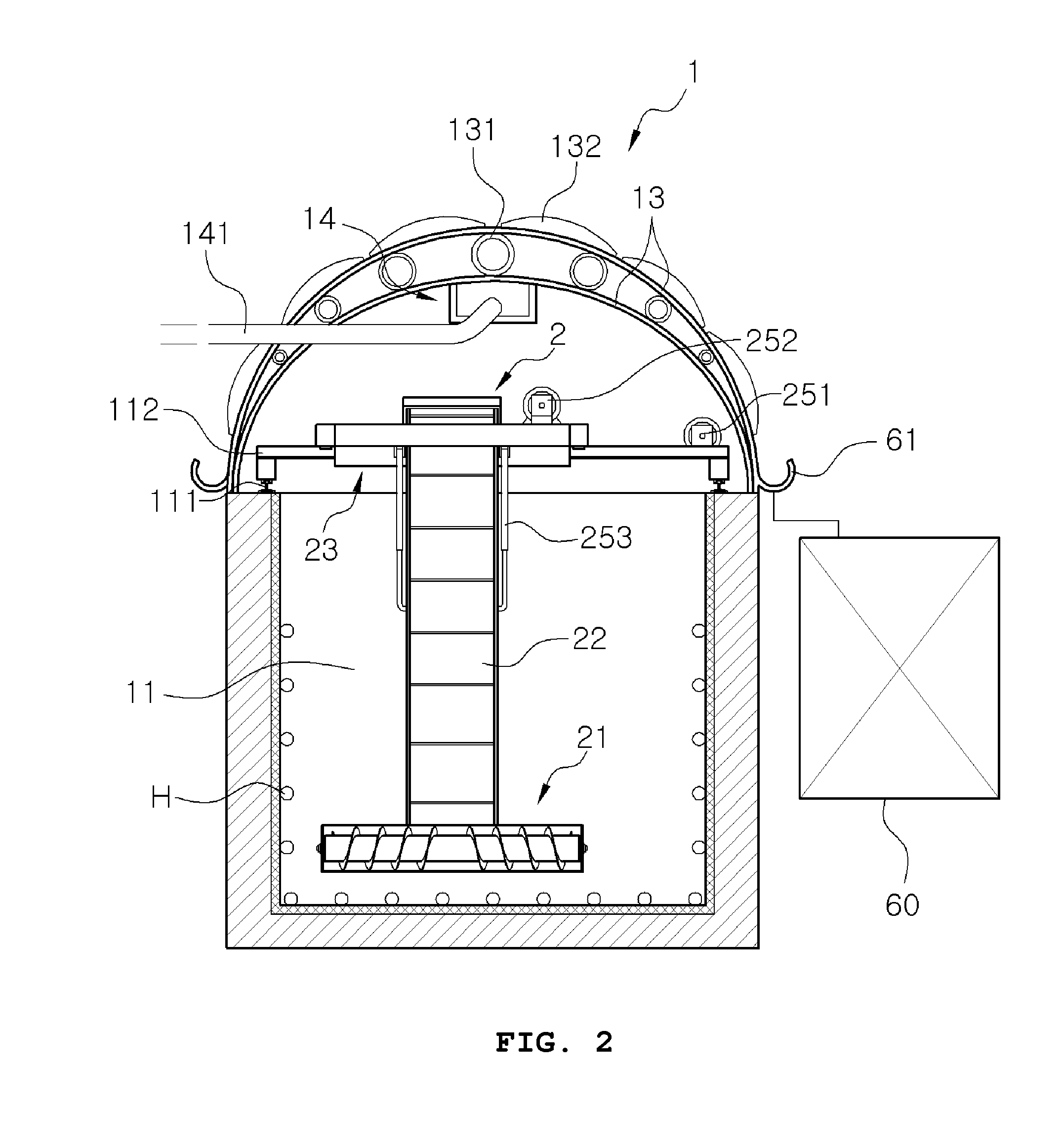
[0035]FIG. 1 is a sectional view illustrating a configuration of a dry anaerobic composting facility according to the present invention, FIG. 2 is a front sectional view illustrating a configuration of a dry anaerobic fermentation unit of FIG. 1, FIG. 3 is a side view of the dry anaerobic fermentation unit ofFIG. 2, FIG. 4 is a perspective view illustrating an agitator shown in FIG. 1, and FIG. 5 is a block diagram illustrating the agitator. As shown in FIGS. 1 to 5, the present invention provides a dry anaerobic composting facility 9 which converts organic waste into anaerobic low-molecular weight compounds through hydrolysis and acid fermentation in a pre-treatment unit connected to a dry anaerobic fermentation unit and then supplies the organic waste to the dry anaerobic fermentation unit before fermenting the organic waste b...


PUM


Abstract

Disclosed is a dry anaerobic composting facility. More specifically, disclosed is a dry anaerobic composting facility which mixes organic waste with a water controller by a pre-treatment unit, followed by pressing, grinding and substitution to convert the organic waste into an anaerobic substance, continuously subjects the anaerobic compound to fermentation, mixing / grinding, transport and discharge using an agitator by an anaerobic fermentation unit to improve production of compost, ages the produced compost by a post-aging unit to provide high-quality compost, and collects biogas produced by the anaerobic fermentation unit and uses the biogas as an energy source of a self-generator or a combined heat and power generator, to realize energy self-generation.

Description

BACKGROUND OF THE INVENTION[0001]1. Field of the Invention[0002]The present invention relates to a dry anaerobic composting facility. More specifically, the present invention relates to a dry anaerobic composting facility which mixes organic waste with a water controller in a pre-treatment unit, followed by pressing, grinding and substitution to convert the organic waste into an anaerobic substance, continuously subjects the anaerobic compound to fermentation, mixing / grinding, transport and discharge using an agitator in an anaerobic fermentation unit to improve production of compost, ages the produced compost in a post-aging unit to provide high-quality compost, and collects biogas produced by the anaerobic fermentation unit and uses the biogas as an energy source of a self-generator or a combined heat and power generator to realize energy self-generation.[0003]2. Description of the Related Art[0004]In recent years, biogas such as methane produced through anaerobic digestion of org...

Claims


Application Information

Patent Timeline
IPC IPC(8): C12M1/16C12M1/34C12M1/02C12M1/00C12M1/107
CPCC12M21/16C12M23/58C12M23/36C12M23/18C12M23/38C12M41/30C12M45/06C12M27/00C12M41/40C12M41/12C12M29/22C12M21/04C12M23/34C12M27/02C12M47/18Y02E50/30Y02W30/40
Inventor CHOI, HONG LIM
Owner RESOURCIFICATION RES CENT FOR CROP ANIMAL FARMING
Learn More