
Passive way to improve heat distribution in packed bed storage

Inactive Publication Date: 2015-10-22
SIEMENS AG
View PDF6 Cites 9 Cited by
  • Summary
  • Abstract
  • Description
  • Claims
  • Application Information

AI Technical Summary

Benefits of technology

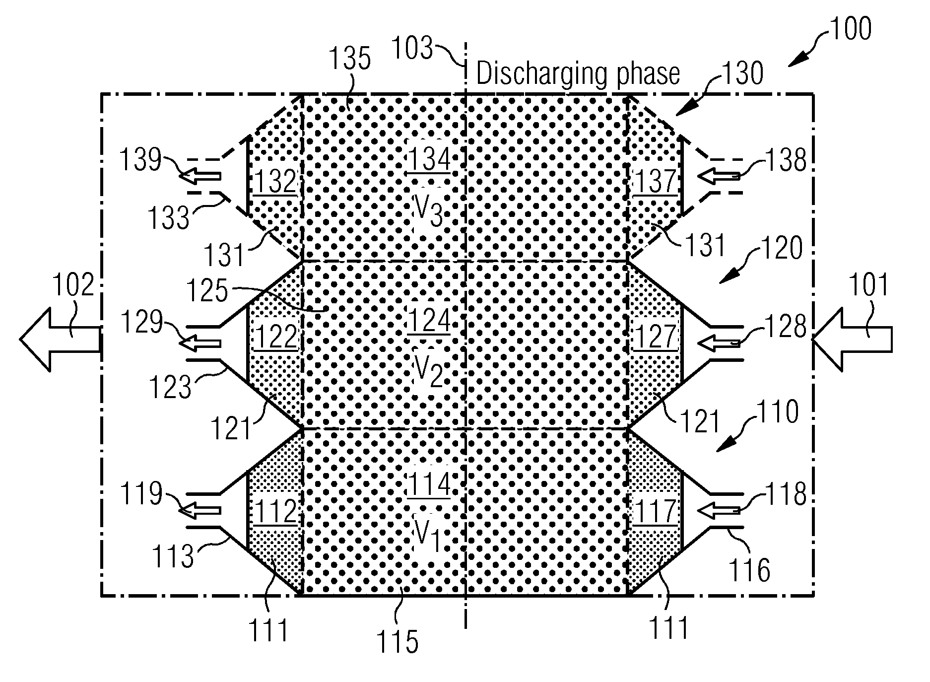
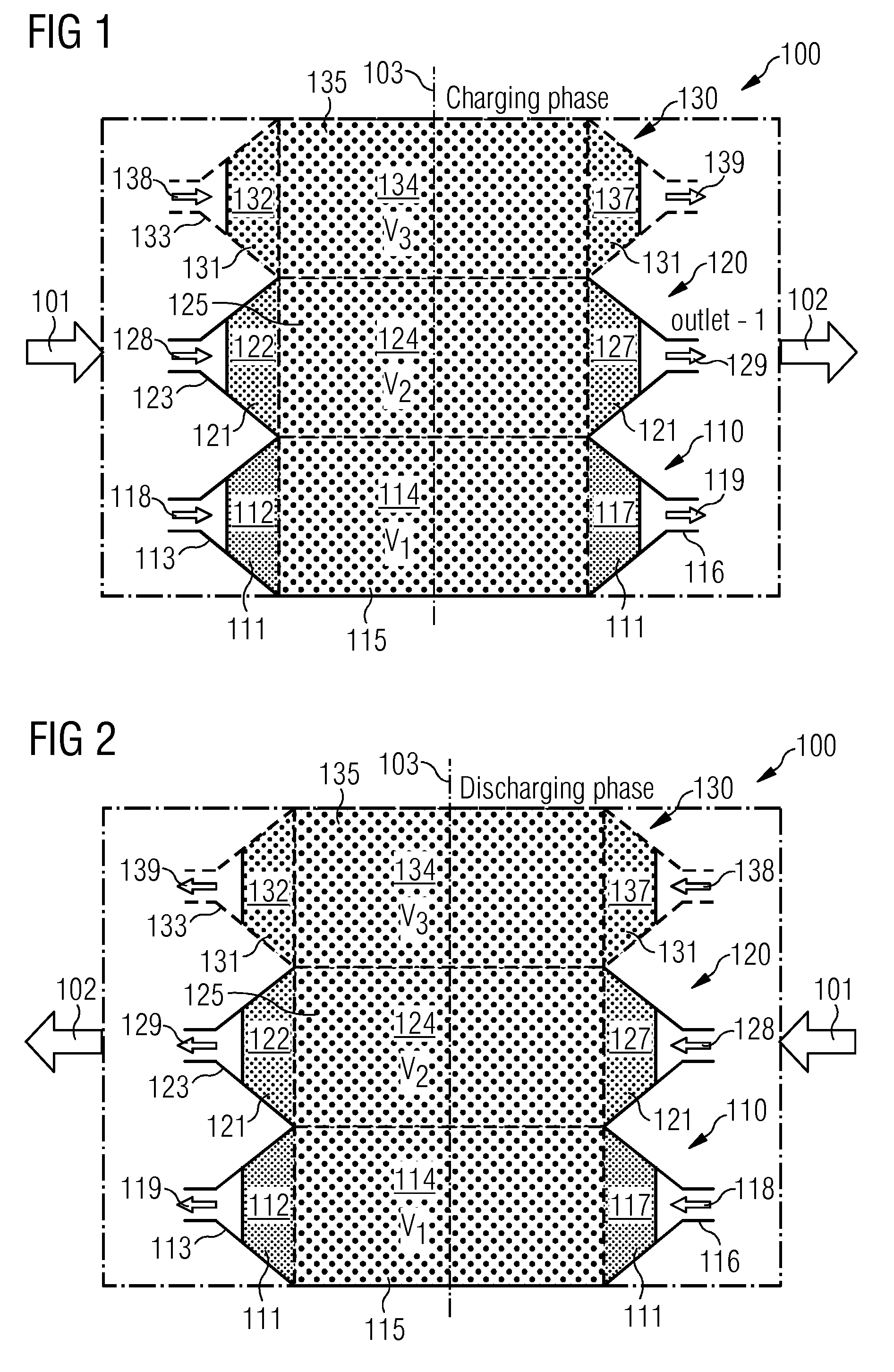
The present invention is a system with a housing that has two sections, made of metal material, and is surrounded by an insulation layer to reduce convection. The system also includes diffusors and confusors to improve the distribution of the working fluid. By filling the openings of the housing with heat storing elements of different diameters, the system can regulate the mass flow through different sections and improve the efficiency of the thermal storage system during charging and discharging phases. The system is passive, meaning no moving or regulated parts, and uses the storage material itself without additional components.

Problems solved by technology

The declination of the angle of the isothermals in the storage medium to the flow direction of the working fluid is strongly dependent on the building / storage height and leads to an increase of temperature discrepancies in the inlet and outlet sections of the storage during the dynamic phases and thus to a decrease of the average outlet temperature leaving the system through the outlet section.

Method used


Image

  • Passive way to improve heat distribution in packed bed storage
  • Passive way to improve heat distribution in packed bed storage

Examples


Embodiment Construction

[0050]The illustration in the drawings is in schematic form. It is noted that in different figures, similar or identical elements are provided with the same reference signs.

[0051]FIG. 1 and FIG. 2 show a schematic view of a storage system 100 according to an exemplary embodiment of the present invention. The system 100 comprises a first housing section 110 with a first storage volume V1, wherein the first housing comprises a first opening 113 for connecting the first storage volume V1 to an environment. A first type 111 of first heat storing elements is arranged within the first housing section 110. The system further comprises a second housing section 120 with a second storage volume V2, wherein the second housing section 120 comprises a second opening 123 for connecting the second storage volume V2 to the environment, wherein the first storage volume V1 and the second storage volume V2 are interconnected for forming a common storage volume. A second type 121 of second heat storing...


PUM


Abstract

A system for storing heat is provided having a first housing section with a first storage volume, wherein the first housing has a first opening for connecting the first storage volume to an environment. A first type of first heat storing elements is arranged within the first housing section. The system has a second housing section with a second storage volume, wherein the second housing section has a second opening for connecting the second storage volume to the environment, wherein the first and second storage volumes are interconnected for forming a common storage volume. A second type of second heat storing elements is arranged within the second housing section. The first heat storing elements of the first type have a respective first element size, wherein the second storing elements of the second type have a respective second element size. The first element size differs from the second element size.

Description

CROSS REFERENCE TO RELATED APPLICATIONS[0001]This application claims the benefit of European Application No. EP14164954 filed Apr. 16, 2014, incorporated by reference herein in its entirety.FIELD OF INVENTION[0002]The present invention relates to a system for storing heat and to a method for manufacturing a system for storing heat.ART BACKGROUND[0003]Nowadays, to improve the efficiency of power plants on the one hand and to smooth network fluctuations caused by the time dependent electrical consumptions on the other hand, integration of thermal energy storages in the power plant system plays a role of increased importance. Several types of thermal energy storages developed recently are available today.[0004]Thermal energy storages are subdivided into the following classes. Solid bed storages which use heat capacity of filled material, liquid thermal storages which use a phase change enthalpy and storages which use chemical reaction enthalpy could provide required storing ability of ...

Claims


Application Information

Patent Timeline
IPC IPC(8): F28D20/00
CPCF28D20/00F28D20/0056F28D2020/0082Y02E60/14
Inventor KOSCHNITZKE, DIRKUSTINOV, VICTOR
Owner SIEMENS AG
Learn More